EasyManua.ls Logo

Bodet Sigma Mod User Manual

Bodet Sigma Mod
65 pages
To Next Page IconTo Next Page
Page #1 background imageLoading...
Page #1 background image
1
Upon receipt, always check the product for damage during shipment. If any is found, you may le a damage
claim with the carrier.
Sigma Mod master clock
SIGMA
Installation and start-up instructions
The document concerns the following products :
907451 Wall Sigma Mod - 110/230V
907452 Wall Sigma Mod - 24V
907453 Rack Sigma Mod - 110/230V
907454 Rack Sigma Mod - 24V
907456 Rack Sigma Mod - 36/72V
BODET SA
BP30001
49340 TREMENTINES
Tél: +33 241 71 72 99
Fax: +33 241 71 72 01
Ref : 606554 ZB
www.bodet-time.com

Table of Contents

Question and Answer IconNeed help?

Do you have a question about the Bodet Sigma Mod and is the answer not in the manual?

Bodet Sigma Mod Specifications

General IconGeneral
BrandBodet
ModelSigma Mod
CategoryClock
LanguageEnglish

Summary

Installation and Start-Up Instructions

General Overview and Product Information

Equipment Checklist for Sigma Master Clock

Details the required components for the SIGMA master clock, including the unit, USB key, and software CD.

Safety Rules and Protections

Electrical Protections and Guidelines

Specifies required circuit breakers and protective measures for various power supply versions and relay circuits.

Installation Safety Precautions

Outlines essential safety measures for cable management, mounting, and general installation practices.

Device Description and Components

Wall-Mounted Sigma Unit Description

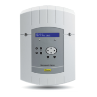
Details the components of the wall-mounted SIGMA master clock, including LCD, keypad, and connectors.

Rack-Mounted Sigma Unit Description

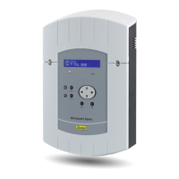
Details the components of the rack-mounted SIGMA master clock, including LCD, keypad, and connectors.

Installation Procedures

Mechanical Installation Guidelines

Provides instructions for choosing a location and physically mounting the SIGMA unit, both wall-mounted and rack versions.

Electrical Connections Diagram

RJ45 Connector LED Status Indicators

Explains the meaning of the green and yellow LEDs on the RJ45 connector for network activity and speed.

D1D2 Distribution Connection

Connecting Melodys Devices

DHF Transmitter Connection

Installation Examples and Configuration

Configuring 24V Time Distribution

Step-by-step guide to setting up a 24V time distribution output, including technician menu settings.

Configuring DHF Time Distribution

Step-by-step guide to setting up a DHF time distribution, including INIT and START modes.

Programming RHF Wireless Circuits

Installing Sigma Option Boards

Setting a 24V TBT Output

Keypad Functions and Navigation

SIGMA Master Clock Keypad Functions

Details the function of each key on the SIGMA master clock keypad, including navigation and special function keys.

Main Menu Programming Guide

Standby State Display Information

Explains the information displayed on the SIGMA in standby mode, including time, date, and holiday indicators.

Accessing and Navigating the User Menu

Instructions on how to access the user menu, enter access codes, and navigate available options.

USB Loading and Backup Procedures

Adding DHF Receivers to the System

Configuring Bank Holidays

Setting and Managing Access Codes

Setting Time and Date

Viewing Radio Reception Status

Selecting Display Language

Viewing SIGMA Software Version

Programming the Circuits

Understanding Circuit Statuses

Defines the different statuses for SIGMA control circuits, such as STOP, START, DISPLAY, PROG, DELETE, and STATUS.

Viewing Circuit Program Details

Programming Circuit Modes

Adding Program Steps to Circuits

Deleting Program Steps from Circuits

Modifying Program Steps in Circuits

Deleting Entire Circuit Programs

Viewing Circuit Operational Status

Manual Circuit Testing Procedures

Programming for Holidays and Special Days

Technician Menu Programming

Technician Menu Options Overview

Lists the various advanced functions available within the technician menu, such as Time Sync, IP config, and Relay assignment.

Time Synchronization Configuration

Programmable Summer/Winter Time Changeovers

Setting the Time Base Drift

Time Output Management

IP Network Configuration

Relay Assignment Configuration

RHF Circuit Function Assignment

External Input Function Settings

Deleting All Programming

Updating SIGMA Software

Restoring Factory Settings

Program Execution Priority

Alarm Messages and Acknowledgement

Optional Expansion Boards

Mechanical Installation of Option Boards

Instructions for physically installing option boards into both wall-mounted and rack-mounted SIGMA units.

Option Board: 3 AFNOR Outputs

Option Board: 2 ASCII Outputs

Option Board: Impulse Outputs

Option Board: 2 Serial Outputs (24VDC)

Option Board: 2 Serial Outputs (48VDC)

Relay Option Board

Option Board: AFNOR Input

Three Inputs Option Card

Technical Characteristics

NTP Programming Guide

Supported IP Network Configuration and Protocols

Troubleshooting Common Issues

Related product manuals