10
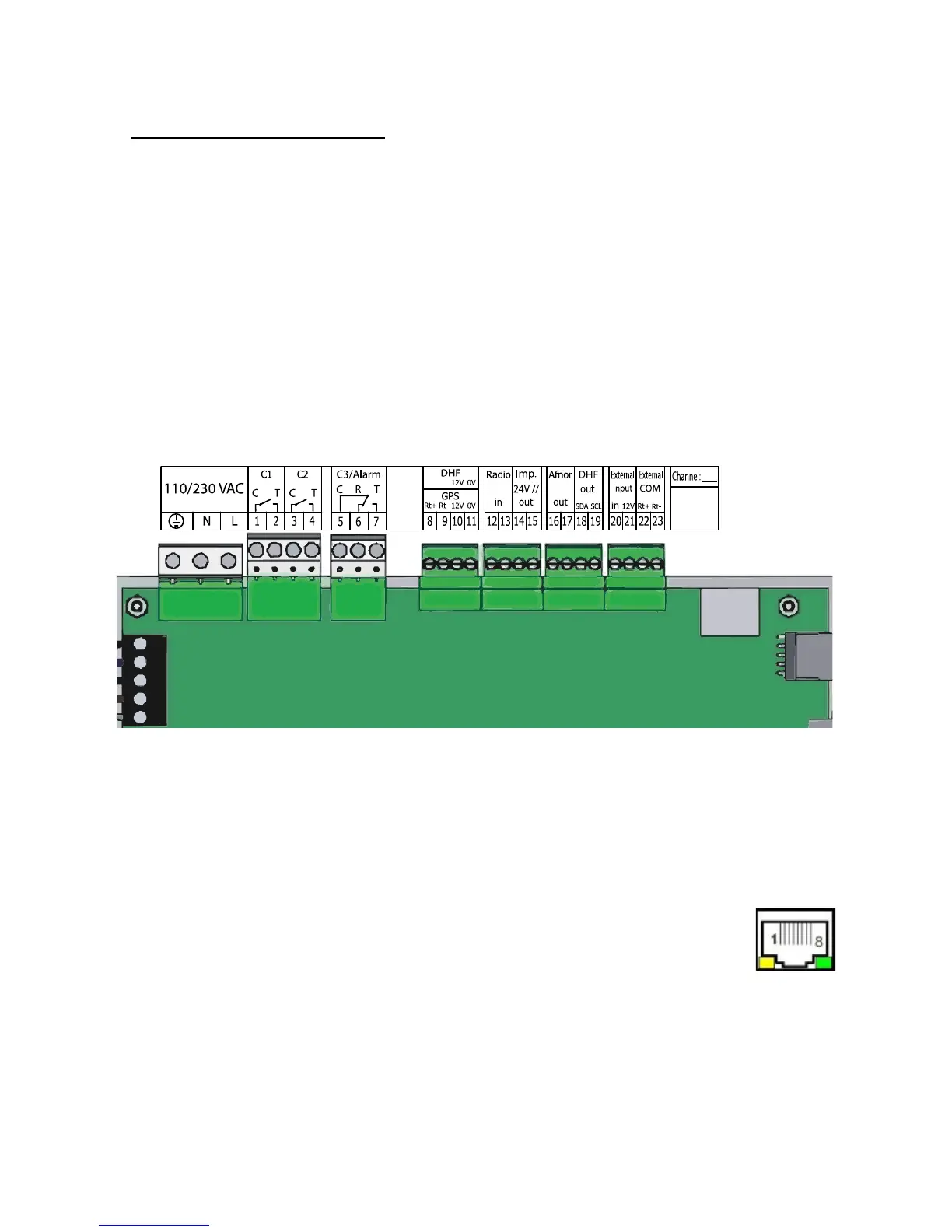
4.2 Electrical connections
Connect the cables (mains power supply, impulse line or AFNOR output and
radio synchronisation input, depending on the model) to the corresponding
terminal strips as shown in the gure below.
(*) See page 33, the “Time outputs” menu to set this output (Pulse minute,
½ minute, second 24V or power TBT 24VDC 1A).
(**) Power supply depending on the version of SIGMA master clock.
Meaning of status of LEDs on RJ45 connector :
- The green LED reects network activity.
- The yellow LED indicates the speed of the network:
off=10 Mbps on=100 Mbps.
RACK version: The mains power supply, impulse line and AFNOR output and
radio synchronisation input terminal strips are directly accessible at the rear of
the Rack slide-in unit.
(**) 110 to
230VAC or
24VDC
or
36/72VDC
Circuit C1
Circuit C2
Circuit C3
GPS input
DCF
radio input
(*) Minute, ½ mn or
second 24V, or SR2-59
Afnor output
DHF output
External input
See the limit
characteristics of
these circuits on
page 59
Attach the wires to each other, near
the terminal strips.
IP connection