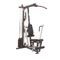
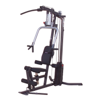
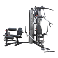
A. Attach one Pulley (26) to Main Base Frame (A) and two Pulleys to Side Base Frame (B) as
shown using:
Three 76 (3/8”x 1 3/4” hex head bolt)
Six 94 (3/8” washer)
Three 91 (3/8” nylon lock nut)
B. Attach one Pulley (26) and Pulley Cable Guide (7) to the middle of the Main Base Frame (A)
as shown using
One 76 (3/8”x 1 3/4” hex head bolt)
Two 94 (3/8” washer)
One 91 (3/8” nylon lock nut)
C. Attach Front Vertical Frame (F) to Main Base Frame (A) as shown using:
Two 64 (1/2”x 3 1/4” hex head bolt)
Four 93 (1/2” washer)
Two 90 (1/2” nylon lock nut)
D. Attach Top Main Frame (G) to Front Vertical Frame (F) as shown using only one bolt:
One 62 (1/2”x 5” hex head bolt)
Two 93 (1/2” washer)
One 90 (1/2” nylon lock nut)
E. Attach Top Main Frame (G) and Pec Dec Frame (H) to Rear Vertical Frame (E) using:
One 65 (1/2”x 3” hex head bolt)*
One 64 (1/2”x 3 1/4” hex head bolt)
Three 93 (1/2” washer)
One 90 (1/2”nylon lock nut)
*NOTE:
The top bolt (65) goes into an internally threaded nut inside the Top Main Frame (G).
2
Be careful to assemble all components
in the sequence they are presented.
STEP
mm
Inch
NOTE:
Finger tighten all hardware in this step. Do Not
wrench tighten until end of step 5.
12