20
Be careful to assemble all components
in the sequence they are presented.
STEP
mm
Inch
NOTE:
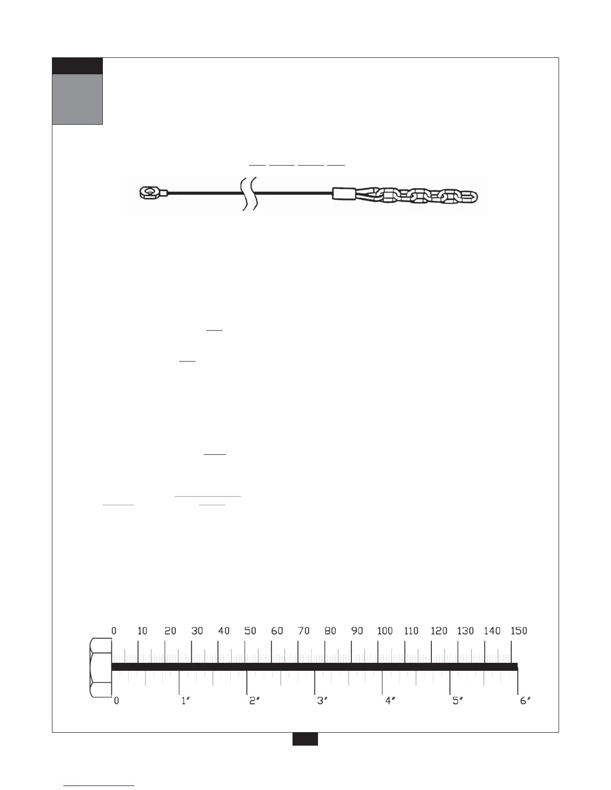
All pulleys are the 4 1/4” diameter Pulleys (26), except where noted.
Leg Press Cable (34)
A. Attach the chain end of Leg Press Cable (34) to Leg Press Frame (BB) with Snap Link (43).
B. Route Cable (34) into the top of pulley housing in Leg Press Pivot (BD) as shown and
install Pulley (F1) using:
One 75 (3/8”x 2” hex head bolt)
Two 94 (3/8” washer)
One 91 (3/8” nylon lock nut)
C. Route Cable (34) over
Pulley (F2) as shown.
D. Route Cable (34) back into the bottom of pulley housing in Leg Press Pivot (BD) and install
Cable (34) over
Pulley (F3) using:
One 75 (3/8”x 2” hex head bolt)
Two 94 (3/8” washer)
One 91 (3/8” nylon lock nut)
E. Route Cable (34) through the opening in the support column of Leg Press Frame (BB).
Pull entire length of Cable (34) through.
Route Cable (34) around Pulley (F4) as shown and toward Pulley (F5).
F. Route Cable (34) under
Pulley (F5) and up to the bottom of Pulley Holder With Hook (133).
Attach Cable (34) to Pulley Holder With Hook (133).
Note:
You should now wr
ench tighten all bolts and nuts.
Except
the pad bolts, Never re-tighten any pad bolts.
48
Chain EndStamped Eye End
4270mm 14’