12
S T E P
2
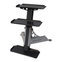
Be careful to assemble all components
in the sequence they are presented.
NOTE: Tighten all hardware at the end of this step.
Some components may be pre-installed.
A. Insert two End Caps (39) into Carriage (H).
B. Insert four End Caps (38) into Carriage (H).
C. Insert two End Caps (29) into Carriage (H).
D. Insert four End Caps (30) into Carriage (H).
E. Unscrew both Allen Screws (13) from Carriage (H) to loosen Shaft (48).
F. Slide Shaft (48) out of Carriage (H).
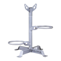
G. Connect Adjustable Plate (K) to Carriage (H) by using:
Two 41 (copper spacer)
One 48 (shaft)
One 45 (torsional spring)
One 46 (torsional spring)
NOTE: Make sure Torsion Springs (45) and (46) are inserted as shown.
H. Tighten both Allen Screws (13) in Carriage (H).
 Loading...