24
S T E P
8
Be careful to assemble all components
in the sequence they are presented.
NOTE: Tighten all hardware at the end of this step.
A. Connect Head Rest Pad (Z) to Carriage (H) using:
Two 12 (⁄” x 2 ¼” hex head bolt)
Two 26 (M8 spring washer)
Two 25 (M8 washer)
NOTE: Do not over tighten Pad Bolts (12), over tightening will strip the T-nuts pressed into
the wood.
B. Connect Head Rest Pad (Z) to Weight Horn Bar Support Plate (X) using:
One 10 (⁄” x 1” round allen head bolt)
One 26 (M8 spring washer)
One 25 (M8 washer)
NOTE: Do not over tighten Pad Bolt (10), over tightening will strip the T-nut pressed into
the wood.
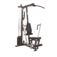
C. Congratulations!! The assembly of your GLPH1100 is now complete.
 Loading...