Product description 2.2 Function description
Page 12 BOGE Operating instructions for C 10 L...C 20 L series screw compressors
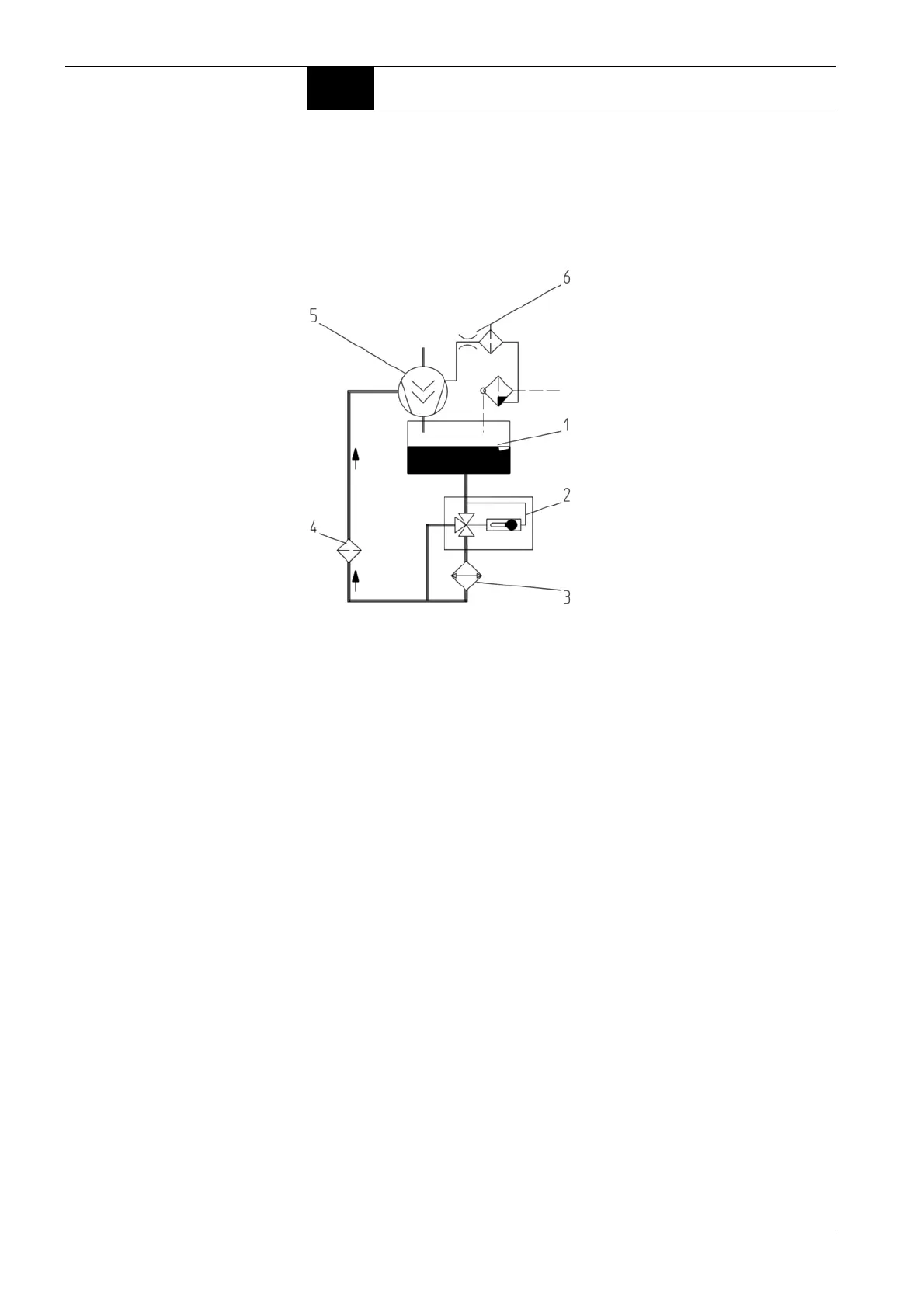
Oil circuit
The oil injected into the air end has the following function:
– It dissipates the compression heat (cooling).
– It seals the gaps between the screws and between screws and housing.
– It lubricates the bearings.
Fig. 2.2: Components of the oil circuit
1 Compressed air/oil separation chamber
The oil separated from the compressed air through the force of gravity col-
lects in the compressed air/oil receiver.
The system pressure forces it out of the receiver into the air end.
2 Thermostatic oil control valve
Depending on the oil temperature, the thermostatic oil control valve either
allows the oil to pass through the oil cooler or through a bypass (e.g. in
the starting phase).
Thus the oil constantly maintains its optimum operating temperature.
3 Oil cooler (air or water cooled)
The oil cooler cools down the hot oil to operating temperature.
4 Oil filter
The oil filter traps impurities in the oil.
5 Air end
The injected oil returns to the compressed air/oil receiver together with the
compressed air. There, it is separated through the force of gravity.
6 Drainage line with dirt trap
The air end suctions the residual oil which collects in the oil separator
back into the oil circuit via a drainage line.
 Loading...