Section 06 DRIVE TRAIN
Subsection 03 (REAR AXLE)
06-03-2
RIGID AXLE
Removal
Lift rear of the vehicle until rear shock absorbers
are fully extended. Install jack stands under frame
to support vehicle.
Remove the rear wheels.
Remove lower shock absorber bolts and elastic
flanged nuts.
1. Lower shock absorber bolts
Remove rear brake caliper and detach brake hose
from bracket on rigid axle no. 1.
CAUTION: Don’t let caliper hang by the hose
and don’t stretch or twist brake hose.
Disconnect vent tube no. 8 on rigid axle.
1. Brake hose
2. Vent tube
Remove the M8 x 10 flanged bolts no. 4 retaining
protector no. 2 under rear rigid axle center sec-
tion.
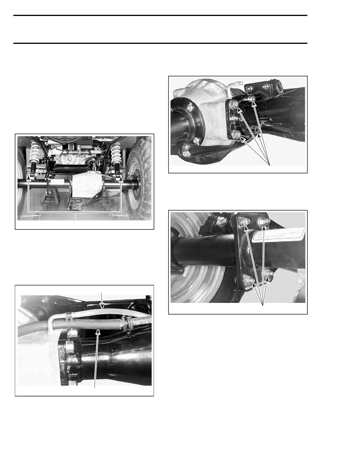
Remove the M10 x 25 socket screws no. 7 retain-
ing rigid axle center section to swing arm.
1. Remove M10 x 25 socket screws
Remove the M10 x 25 flanged bolts no. 5 and
elastic flanged nuts no. 6 retaining swing arm to
rigid axle.
1. Remove flanged bolts and elastic flanged nuts
Detach rigid axle from swing arm.
Installation
Installation is essentially the reverse of removal
procedure. Paying attention to the following de-
tails.
Apply grease (P/N 293 550 019) on the spring to
the end of the propeller shaft.
Secure rear rigid axle center section to swing arm
with socket screws. Apply sealant Right Stuff (P/N
293 800 053) between both parts. Do not tighten
yet.
1
V01J03B
V01J04A
1
2
1
V01J05A
1
V01J06A

 Loading...