Section 07 STEERING/CONTROL SYSTEMS
Subsection 02 (STEERING/CONTROL SYSTEMS)
07-02-2
HANDLE BAR
Removal
Remove:
– steering cover (refer to BODY 10-02)
– handle bar grips no. 1 (discard screws)
– brake handles no. 2. (refer to HYDRAULIC BRAKES
09-02)
– throttle handle no. 3 and multi-function switch
no. 4 (refer to the specific section)
– steering clamp mounting bolts no. 5 and steer-
ing clamp no. 6
– handle bar no. 7
Inspection
Inspect the handle bar for damage, cracks or bend-
ing, replace if any problems is detected.
Installation
For the installation, reverse the removal procedure.
NOTE: Replace screws retaining handle bar grip by
a new self-locking screws.
STEERING COLUMN
Removal
Remove:
– steering cover (refer to BODY 10-02)
– steering clamp mounting bolts no. 5, steering
clamp no. 6 and steering cover support no. 8
– fuel tank (refer to FUEL CIRCUIT 04-02)
NOTE: Do not remove fuel tank completely, sep-
arate fuel tank from frame only. Do not remove
fuel lines.
– cotter pin no. 9, castellated nut no. 10 and flat
washer no. 11 to bottom end of steering col-
umn no. 12
Separate steering column and tie-rods no. 13. Re-
fer to TIE-ROD section.
Remove half housing bolts no. 14, stopper plates
no. 15, half housings no. 16 and housing bushings
no. 17.
Pull steering column.
Inspection
Inspect steering column for damage, cracks or bend-
ing, replace if any problems is detected.
Installation
For the installation, reverse the removal procedure.
TIE-ROD
Removal
Place the vehicle on jack stands and remove front
wheel(s).
Remove front fender. Refer to BODY 10-02.
Remove fuel tank. Refer to FUEL CIRCUIT 04-02.
NOTE: Do not remove tank completely, separate
fuel tank from frame. Do not remove fuel lines.
Remove cotter pin no. 18, castellated nut no. 19,
hardened washer no. 20 and flat washer no. 21.
Inspection
Inspect ball joint ends for wear or looseness, if ex-
cessive, replace.
Installation
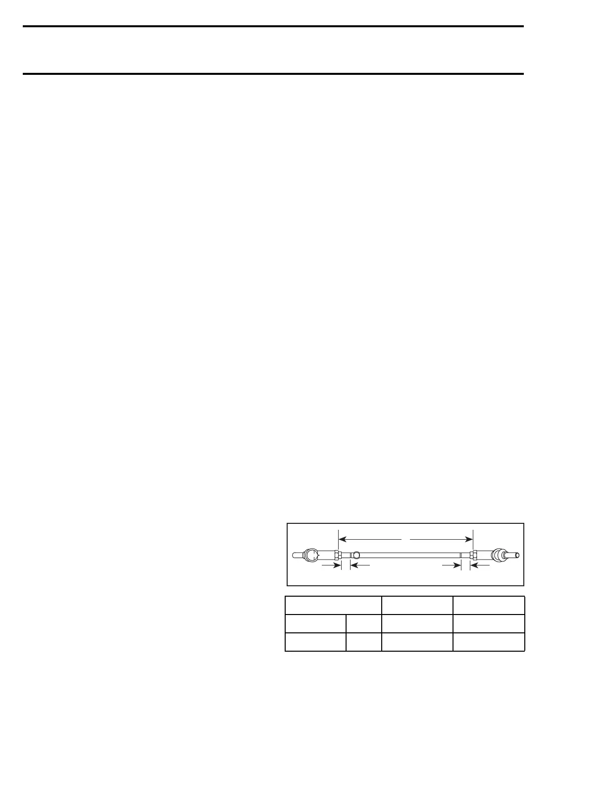
For the installation, reverse the removal proce-
dure. Pay attention to the following details.
At the time of the reinstallation or the new tie-
rod(s) installation, screw threaded end of tie-rod
into ball joint. The maximum length for tie-rod
groove to ball joint end must be the value A in the
following chart:
NOTE: Torque the ball joint lock nut no. 22 to 36
N•m (27 lbf•in).
MODEL A B
mm 20 ± 5 311 ± 1
TRAXTER in 25/32 ± 0.197 12 1/4 ± 0.039
B
V01I0YA
AA

 Loading...