Section 03 ENGINE
Subsection 02 (REMOVAL AND INSTALLATION)
03 02 2
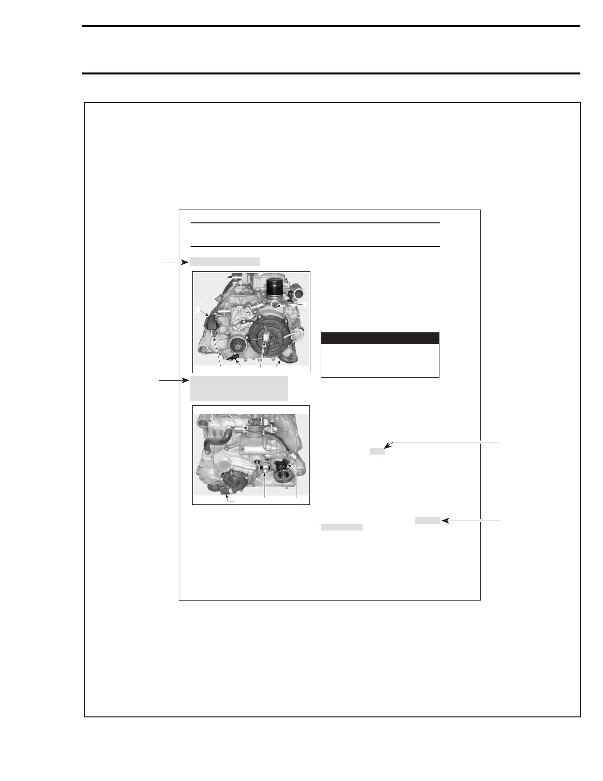
1 Shifting valve
2 GBPS (Gear Box Pos tion Sensor)
3 Magneto/Trigger plug
4 Engine coolant hose
Place the vehicle on jackstands and place the shifter
no. 1
on park position
Remove front wheels
Drain engine oil and engine coolant
Remove seat, front and rear fenders, inner fend-
ers, side panels, steering cover, shifter guide cov-
er and skid plate Refer to the section 09-02 BODY
Disconnect BLACK negative cable from battery,
then RED positive cable
Front Part Preparation
Remove fuel tank and fuel valve Refer to the sec-
tion 03-02 FUEL CIRCUIT
Disconnect the interlock cable
no. 2
under shifter
lever
Remove seat pivot bar and unplug the clutching
and clutch modulator valves connector
Remove the STPS (Sub Transmission Position Sen-
sor)
ROD REMOVAL section
Remove front propeller shaft Refer to the section
05-02 FRONT DIFFERENTIAL
Unplug the VSS (Vehicle Speed Sensor), located
under engine drive shaft
Engine Preparation
Unplug spark plug cables
Unplug oil pressure sensor
Remove radiator inlet hose
Remove breather` hose
Unplug the temperature sensor
WARNING
Always disconnect battery or starter cables
exactly in the specified order, BLACK nega-
tive cable first. It is recommended to discon-
nect electrical connections prior to discon-
necting fuel lines.
2
V01C0DA
431 6
5
1
3
V01C0EA
24
Vehicle Preparation
2 STPS (Sub Transmission Position Sensor)
3 VSS (Vehicle Speed Sensor)
4 Shifting engine rod
5 Oil pressure sensor
6 Engine coolant hose
1 Clutching and clutch modulator valves connector
Remove exhaust pipe
no. 5
Refer to the EXHAUST
SYSTEM section
Remove shifting rod
no. 3
Refer to the SHIFTING
ENGINE REMOVAL
m
TYPICAL PAGE
Title indicates
main procedure
to be carried out.
Reference to look
up a certain section
and subsection.
In this case it
concerns
exhaust system.
Bold face number
following part
name refers to
exploded view
at beginning of
subsection.
Call outs for
above illustration.
V01A0RS
INTRODUCTION

 Loading...