ASSEMBLY INSTRUCTIONS
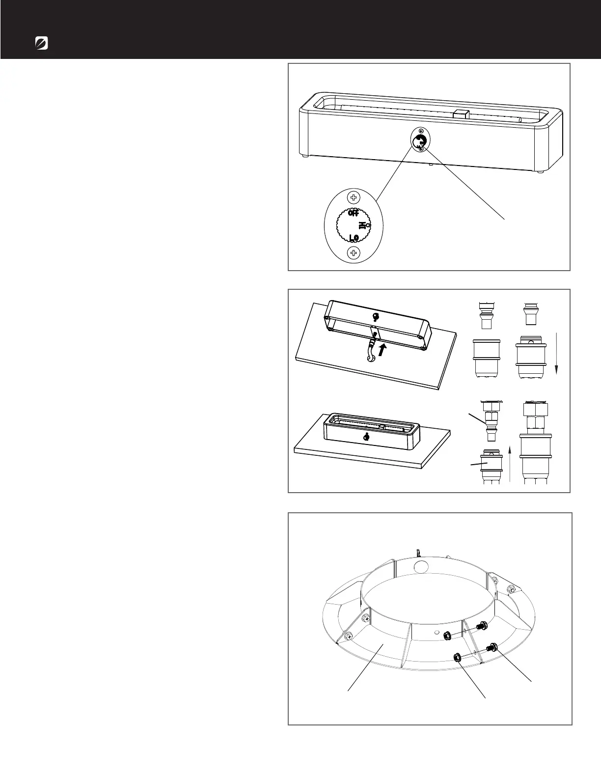
1. Check that the control knob ( H ) for the
gas supply system is turned to the “OFF”
position before starting any assembly.
2.
H
222
1
C
D
AA
BB
3.
1-866-771-2663 | Page 7
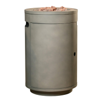
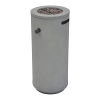
I
Attach 4 pcs tank holder parts (I) together
using 8 pcs M6x10 screws (AA) and 8 pcs
M6 nuts (BB) as shown in the diagram.
Insert the female end of quick disconnect
connection (D) from the underneath and
through the umbrella hole on the table.
Pull back and hold the collar on the
female end of the quick disconnect
connection (D) coupling. Insert the
quick disconnect male end (C) fully
into the coupling and then release
the collar. Place the product on
the table.