06/0550
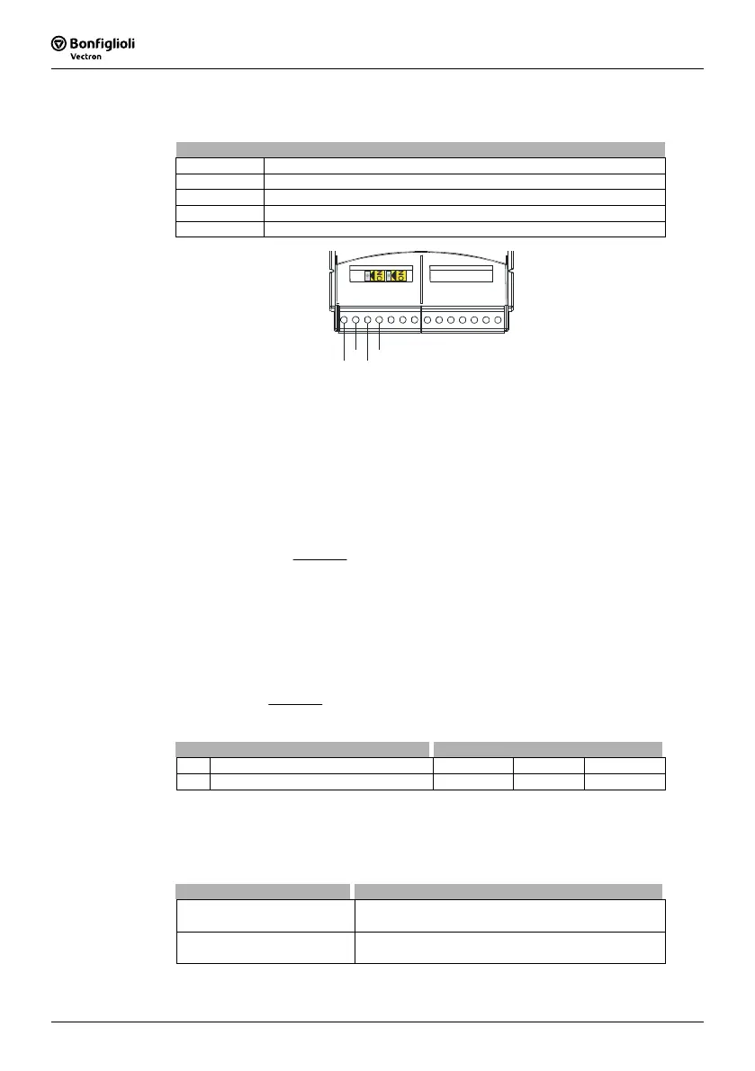
assignment of the inputs:
Socket X410A
Terminal input
(1): X410A.1 Speed sensor input EM-ENC track A+
(2): X410A.2 Speed sensor input EM-ENC track A-
(3): X410A.3 Speed sensor input EM-ENC track B+
(4): X410A.4 Speed sensor input EM-ENC track B-
X410A
X410B
1
2
3
4
5.1.2 Division marks
The number of increments of the connected speed sensor can be parameterized via
the parameter
Division marks speed sensor 2 494. The number of division marks of
the speed sensor is to be selected according to the speed range of the application.
The maximum number of division marks S
max
is defined by the limit frequency of f
max
=
300 kHz of the speed sensor inputs EM-ENC (track A) and EM-ENC (track B).
max
max
n
s/min60
Hz000300S ⋅=
n
max
= Max. speed of the motor in RPM
To ensure a good true running of the drive mechanism, a sensor signal must be
evaluated at least every 2 ms (signal frequency f = 500 Hz). The minimum number of
division marks S
min
of the incremental speed sensor for a required minimum speed n
min
can be calculated from this requirement. The evaluation of four signal edges per mark
is firmly defined in the function of speed sensor 2.
min
min
nA
s/min60
Hz500S
⋅
⋅=
n
min
=
A =
Min. speed of the motor in RPM
4 (quadruple evaluation)
Parameter Setting
No. Description Min. Max. Fact. Sett.
494 Division marks speed sensor 2 1 8192 1024
5.1.3 Level
Via the parameter
Operation mode Level 495, the following operation modes can be
selected:
Operation mode Function
0 - push-pull
Push-pull signals (5 V) are evaluated
(according to specification RS-422A/RS-485).
2 - unipolar
Unipolar signals (10 V…24 V) at A+ and B+ are evalu-
ated.