The selected warning mask application can be read out via the parameter Actual
Appl. Warning Mask 627. The above operation modes of parameter Cre
Warning Mask 626 are encoded in the Actual Appl. Warning Mask 627
results from hexadecimal addition of the individual operation modes and the match-
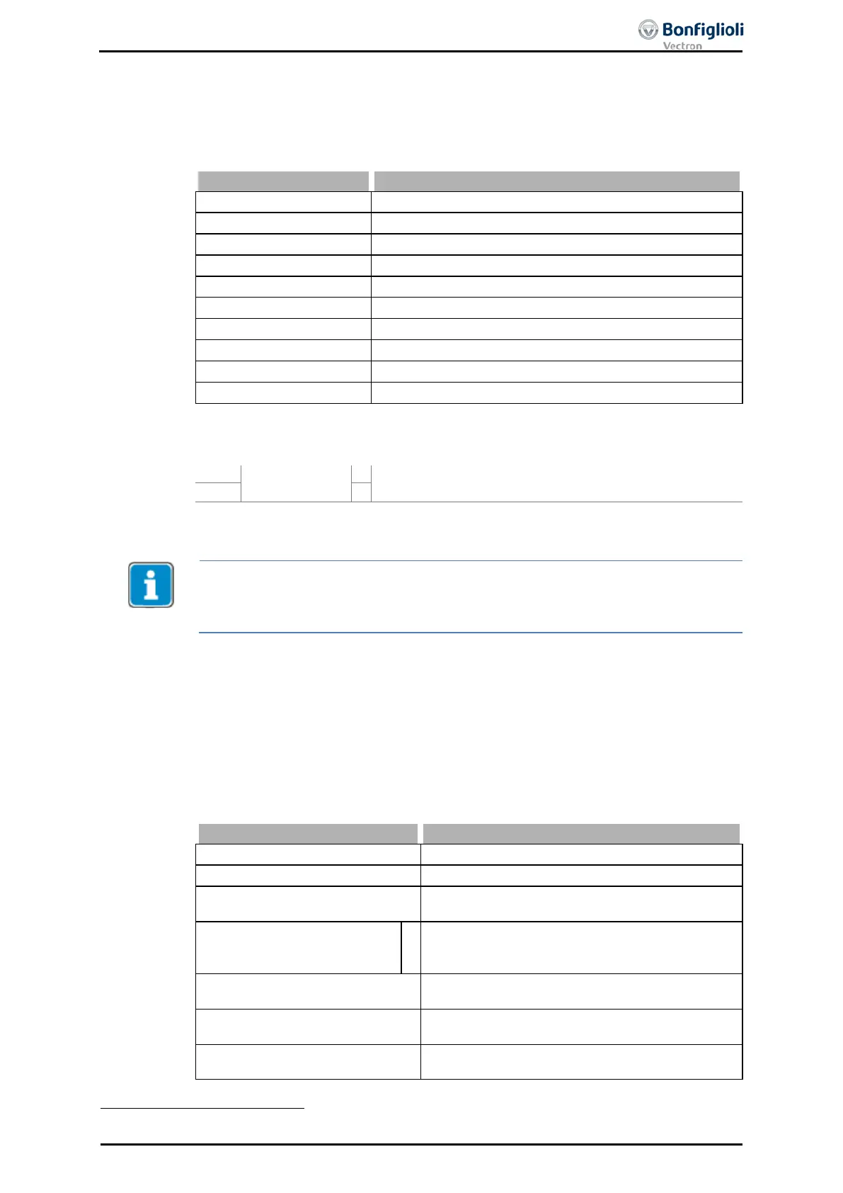
Create Appl. Warning Mask 626
A 003F - 2 -
Activate all Warnings
A 0001 BELT 10 -
Warning V-belt
A 0002 SW-LIM CW 11 -
Warning pos. SW limit switch
A 0004 SW-LIM CCW 12 -
Warning neg. SW limit switch
A 0008 HW-LIM CW 13 -
Warning pos. HW limit switch
Warning neg. HW limit switch
Warning position controller
The output of a warning message is signaled.
Warning Mask,
Application
Output of a warning message which is activated in Cre-
ate Appl. Warning Mask 626.
1)
For linking with inverter functions
Parameter Warning Application 273 shows the Application Warnings independent
from the created Warning mask.
In the error environment,
Application Warning Status 367 shows the current war
n-
ings of the positioning functions independent from the created Warning mask.
15.4 Digital inputs
The assignment of the control signals to the available software functions can be
adapted to the application in question. Depending on the Configuration 30
the default assignment or
the selection of the operation mode differ. In addition to
the available digital control inputs, further internal logic signals are available as
sources.
Each of the individual software functions is assigned to the various signal sources via
parameterizable inputs. This enables a flexible use of the digital control signals.
Signal input is switched on.
7 - Off Signal input is switched off.
13 -
Technology Controller
Start
Start command technology controller (configura-
tion 111, 211 or 411).
70 - Inverter Release
1
Signal on digital input S1IND/STOA (X210A.3)
and S7IND/STOB (X210B.2); the safety function
STO is linked permanently.
71 - S2IND
Signal on digital input S2IND (X210A.4) or re-
mote operation via communication interface.
72 - S3IND
Signal on digital input S3IND (X210A.5) or re-
mote operation via communication interface.
73 - S4IND
Signal on digital input S4IND (X210A.6) or re-
mote operation via communication interface.
1
Refer to the application manual “Safe Torque Off” for further details.
06/13 Operating Instructions ACU 191
 Loading...
