11/06 13
4.2 Fan and liquid cooling
he size of the heat sinks can be reduced if fans are installed or a liquid coolin
system
is used in addition to the "Cold Plate" technology.
The size of the heat sink can be reduced proportionally to the increase in the flow rate
of the cooling medium.
In the followin
a fan coolin
system is described as an example. For calculatin
the
maximum permissible heat resistance R
th enforced
for cooling by means of a fan, a pro-
portionality factor is introduced. This factor describes the increase of the max. permis-
sible thermal resistance at increasing flow rate of the cooling air.
The max. permissible thermal resistance R
th enforced
for enforced air cooling can be calcu-
lated as follows:
α
=
th
enforced th
R
R
R
th
: max. permissible thermal resistance with free circulation of air; calculate according to the
formula for R
th
in the previous chapter or use the value indicated in the table, α: proportionality
factor
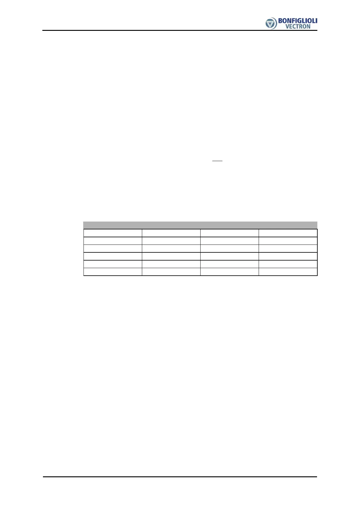
The relation is shown, as an example, in the following table for the ACT401-27 fre-
quency inverter.
Thermal resistance for enforced air cooling
R
th
[K/W] V
air
[m/s]
α
R
th enforced
[K/W]
0.08 0 1 0.08
0.08 1 0.65 0.12
0.08 2 0.45 0.18
0.08 4 0.28 0.29
0.08 6 0.20 0.40

 Loading...


