6 11/06
2 Technical data
The following tables contain the technical data of the frequency inverter series ACT and
ACU in the "Cold Plate" variant. The recommended motor shaft output applies to the
corresponding nominal voltage of the frequency inverter according to the instructions a
a switchin
frequency of 2 kHz. The wei
hts and dimensions differ from the data listed
in the instructions. The dimensions are valid for the frequency inverter without plug-in
terminals and with cold plate in the "Cold Plate" device variant. For the other technical
data refer to the enclosed instructions.
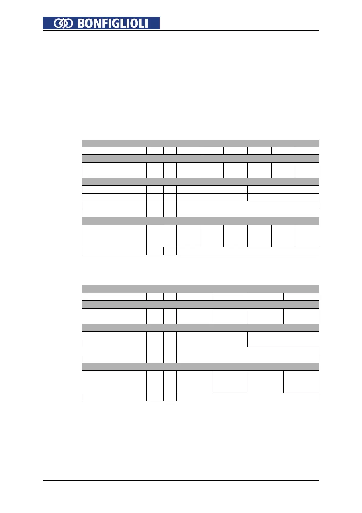
2.1 ACT/ACU 201 (0.55 to 3.0 kW, 230 V)
Type designation
ACT/ACU 201 -05 -07 -09 -11 -13 -15
Motor-side output
Recommended
motor shaft output
P kW 0.55 0.75 1.1 1.5 2.2 3.0
Mechanical
Dimensions
HxWxD
mm 190x82x140 250x85x140
Weight (approx.) m kg 1.2 1.6
Type of protection - - IP20 (EN60529)
Installation position - - vertical
Environmental conditions
Energy dissipation
(at 2 kHz switching
frequency)
P W 43 53 73 84 115 170
Coolant temperature Tn °C 0 ... 40 (3K3 DIN IEC 721-3-3)
2.2 ACT/ACU 201 (4.0 to 9.2 kW, 230 V)
Type designation
ACT/ACU 201 -18 -19 -21 -22
Motor-side output
Recommended
motor shaft output
P kW 4.0 5.5 7.5 9.2
Mechanical
Dimensions
HxWxD
mm 250x125x144 250x150x144
Weight (approx.) m kg 2.2 3.1
Type of protection - - IP20 (EN60529)
Installation position - - vertical
Environmental conditions
Energy dissipation
(at 2 kHz switching
frequency)
P W 200 225 310 420
Coolant temperature Tn °C 0 ... 40 (3K3 DIN IEC 721-3-3)

 Loading...


