Voorhout • Groningen • Weert • Hoogerheide T +31(0)88 7865800 I elsto.eu
Quick Start Guide
Agile
38 05/2013
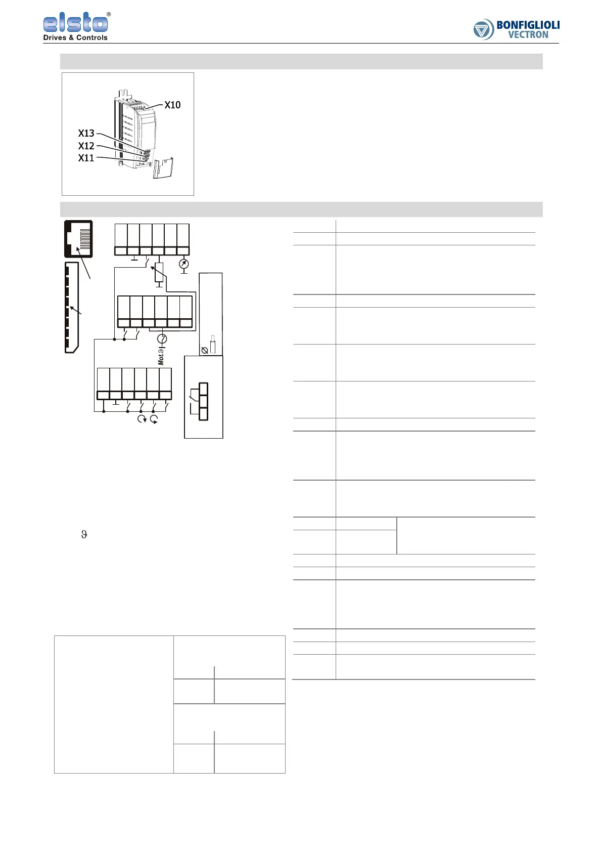
Function of control terminals
− 6 digital inputs, 2 of them for
Enable
− 1 digital input/ output
− 2 multifunction inputs:
digital/analog
− 1 digital output
− 1 multifunction output:
digital/analog/frequency
− 1 voltage input DC 24 V
− 2 voltage outputs,
DC 10 V and DC 24 V
− 1 relay output
− Communication-
interface CAN
Standard control wiring
X13.1 DC 24 V input
X13.2 GND forX13.1
X13.3 Di
ital input. Input 2 for enable. Contact
opened: output disabled, motor coast to
a standstill. Contact closed (together
with X11.3): normal operation..
X13.4 DC 10 V output
X13.5 Di
ital output. Run si
nal. Indicates
output of frequency when enable and
start command applies.
X13.6 Multifunction output. Default: analo
.
Voltage signal proportional to actual
speed. 10 V at 50 Hz,0Vat0Hz.
X12.1 Di
ital input.
Data set change-over together with
X11.6.
X12.2 Di
ital input. Error acknowled
ment.
X12.3 Multifunction input: di
ital/analo
.
Default: analog voltage input. Reference
speed. 50 Hz at DC 10 V, 3.50 Hz at DC
0 V.
X12.4 Multifunction input: di
ital/analo
.
Default: digital input. For connection of
motor thermal contact. Set P570.
X12.5 CAN Hi
h Systembus connection.
Refer to the separate
manual.
X12.6 CAN Low
X11.1 DC 24 V output
X11.2 GND for X11.1
X11.3 Di
ital input. Input 1 for enable. Contact
opened: output disabled, motor coast to
a standstill. Contact closed (together
with X13.3): normal operation.
X11.4 Di
ital input. Start clockwise.
X11.5 Di
ital input. Start anticlockwise.
X11.6 Di
ital input/output. Default: input. Data
set change-over together with X12.1.
Observe the technical data in the manual.
IND:
MFI:
OUTD
OUT2D:
MFO1:
Run Sig.
Act. Speed:
Speed ref:
Mot.
Sys
Enable:
FixedFr.
Dataset
Relay output
Memory card:
Mode:
X:
digital input
multifunction input
digital output
digital output 2
multifunction output
execution message
actual speed
setpoint speedl
motor temperature
CAN-systembus
release
fixed frequency
Dataset
relay output fault message
slot for optional memory card
operation mode for X11.6
terminal strip
Thermal contact
evaluation X12.4
Data set chan
e-ove
P570 0- off (default)
1- Warning
2- Error switch
off
X11.6 Selection
0 DS1
1 DS2
Switchin
frequency
X12.1 Selection
0 0 Hz (P480)
1 10 Hz (P481)
nable A
Enable B
Run Sig.
X21:
Service Port
and RS485
X20: Memory Card
> 4k7
X11:
Start
Start
Dataset 1
FixedFr.1
Err. Quitt
Speedref.
Sys_H
Sys_L
24Vout
(<100mA)
GND
123456
STOA
IN1D
IN2D
IN3D /
OUT3D *
X12:
IN4D
12 3456
IN5D
MFI1
MFI2
CAN H
CAN L
X13:
24Vin
12
3
4
56
GND
STOB
10Vout
OUT1D
MFO1
Act.
Speed
1A DC / 24V
3A AC / 240V
Fault Message
X10:
1 23
OUT2D
Relay output
*Mode via P558
0
.
1
.
.
.
1
.
5
m
m
2
8
.
.
.
1
6
A
W
G
2

 Loading...


