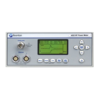
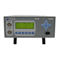
Boonton 4540 Series RF Power Meter
General Information
1.4 Accessories
Optional 4540 accessories that can be ordered from Boonton Electronics.
Table 1-1 Accessories for the 4540 Series
Selection Part Number Description
Standard
56810400A Line Cord (US)
96101301A Fuse Kit
98601300C Manual CD, Boonton Measurement Instruments (CD-ROM)
Optional
54600000A Fuse, USA (1.0A, Type T, 250V)
95403001A Rack Mounting Kit (Brackets only)
95403003A Rack Mounting Kit (Brackets with handles)
95105501A Type N to K Adaptor (for sensors with K-Connector®)
95600005A Peak Sensor Cable - 5 ft. (1.27 m)
95600010A Peak Sensor Cable - 10 ft. (2.54 m)
95600020A Peak Sensor Cable - 20 ft. (5.08 m)
95600025A Peak Sensor Cable - 25 ft. (6.35 m)
95600050A Peak Sensor Cable - 50 ft. (12.7 m)
95109101A CW Sensor Combo Cable/Data Adapter – 5 ft (1.27 m)
95109102A CW Sensor Combo Cable/Data Adapter – 10 ft (2.54 m)
95109001A CW Sensor Data Adapter – with connector for 41-2A cable
41-2A CW Sensor Cable – 5ft (1.27 m)
41-2A/10 CW Sensor Cable – 10ft (2.54 m)
41-2A/20 CW Sensor Cable – 20ft (5.05 m)
41-2A/50 CW Sensor Cable – 50ft (12.7 m)
41-2A/100 CW Sensor Cable – 100ft (25.4 m)
98406100A Instruction Manual 4540 Series, English (Printed w/binder)
Sensors
For sensor selection, refer to the BOONTON Sensor Manual.
1.5 Models, Options and Configurations
Model 4541. One measurement channel; sensor and calibrator connectors located on the front panel.
Model 4542. Two measurement channels; sensor and calibrator connectors located on the front panel.
Opt -02. Configuration option: Sensor connectors are located on the rear panel.
Opt -03. Configuration option: Calibrator connectors are located on the rear panel.
Opt -30. Warranty option: Extend factory warranty to 3 years
Option designations are appended to the instrument’s base model number. For example, Model 4542-02-
03 would be a two-channel instrument with sensor and calibrator connectors all on the rear panel.
Specials. Custom configurations have –S/n appended to the model number, where n is a unique number.


 To Next Page