Boonton 4540 Series RF Power Meter
Getting Started
3.3 LCD Monitor Display
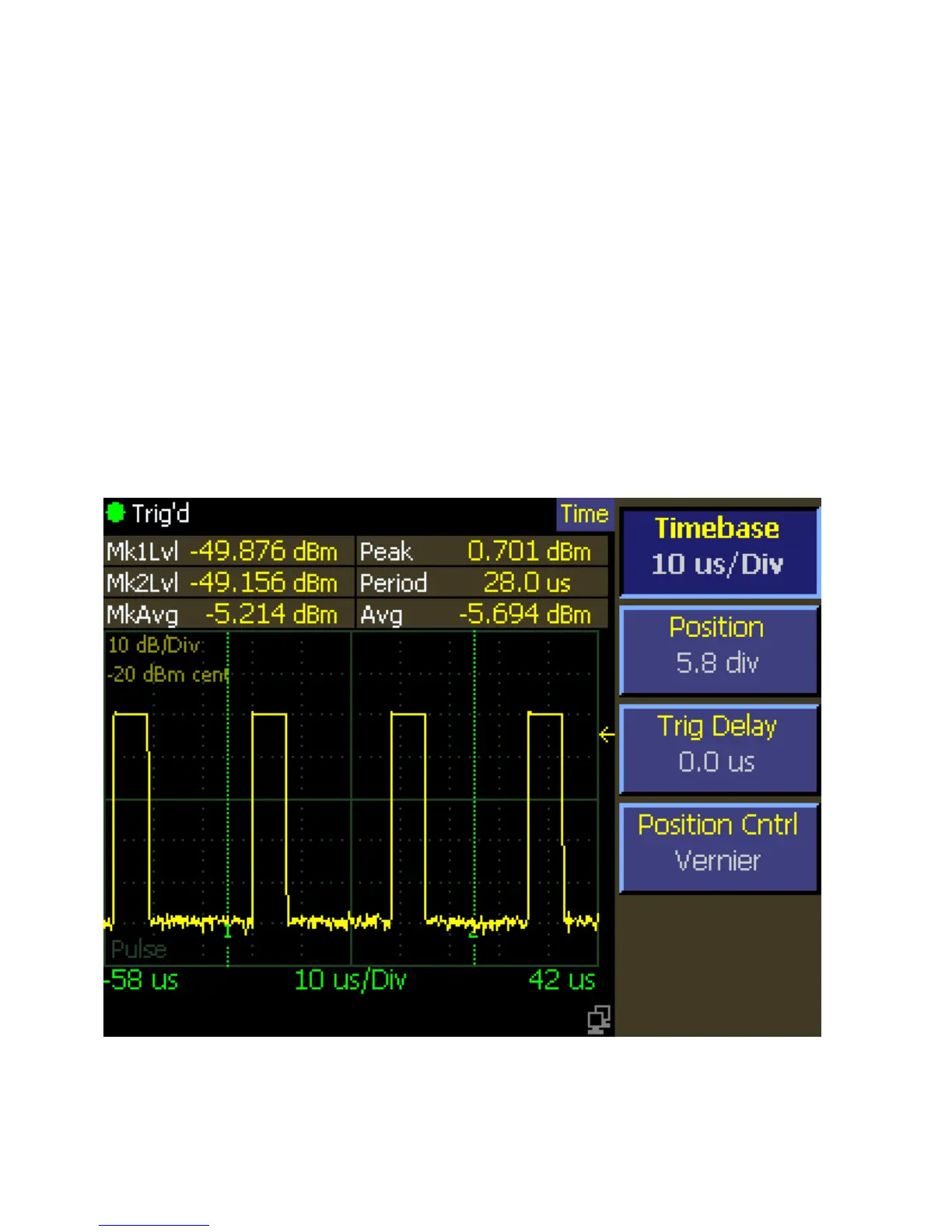
This subsection includes a picture (Figure 3-3) and a table (Table 3-2) of descriptions of the display layout of the 4540 Series.
Figure 3-3a shows the graphics (trace) display mode of the instrument. Figure 3-3b shows the pulse mode text (automeasure)
display mode of the instrument. Figure 3-3c shows the modulated text mode. In addition there are text formats for reports.
See Section 4.5 for more information on the display format.
Table 3-2 LCD Monitor Display Fields
Ref. No. Field Name Mode Description
1 Measurement status All Contains an icon and text indicating the measurement
acquisition status of the instrument.
2 Path name All Lists the all of the menus in the path of the current
menu.
3 Menu All The current menu. The menu may be hidden.
4 Error field All Identifies errors as they occur.
Figure 3-3a. LCD Monitor Graphic Display



 To Next Page