Open the cover to the housing of the activated char-
coal filter [1] from below.
click
1
4
3
2
Fig. 6.16 Hooking in the frame of the exible duct
[1] Retaining groove of the housing of the activated charcoal
filter
[2] Position shackles
[3] Flexible duct frame
[4] Lower lock
Insert the frame of the flexible duct into the retaining
groove of the housing of the activated charcoal filter
[1].
Make sure that both lateral position shackles [2] are in
the guide.
Move the frame upwards [3] until the lower [4] and
upper lock engage in the middle.
Make sure that the frame is inserted into the groove
of the housing [1] on all sides.
1
2
Fig. 6.17 Inserting the activated charcoal lter
[1] Housing cover of the activated charcoal filter
[2] Activated charcoal filter
Remove the packaging from the activated charcoal fil-
ters.
Insert the two activated charcoal filters [2] from
below.
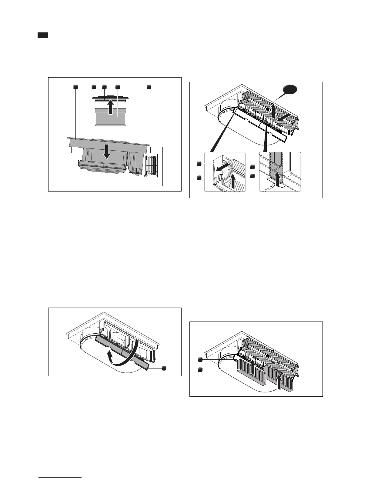
Inserting the cooktop
54321
Fig. 6.14 Insert the cooktop at an angle
[1] Cooktop
[2] Suction opening
[3] Air inlet nozzle
[4] Stainless steel grease filter
[5] Worktop cut-out
Before inserting the device, remove the air inlet nozzle
[3] and the stainless steel grease filter [4].
Use the suction opening as something to grab hold of
during insertion.
Insert the cooktop at an angle into the worktop cut-
out [5]. The glass ceramic panel must be supported
along the entire rear width (e.g. using a strip of wood)
in the process.
1
Fig. 6.15 Opening the housing cover
[1] Housing cover of the activated charcoal filter


 To Next Page