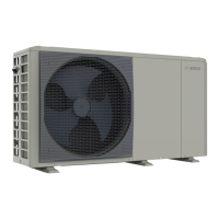
Side cover and transport fitting
17
AW 4 | 5 | 7 OR-S – 6721866761 (2023/06)
6 Side cover and transport fitting
▶ Remove the side cover.
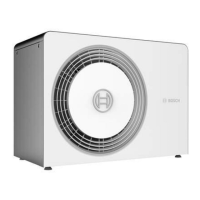
Fig. 29 Side cover
The heat pump is equipped with a transportation screw. The
transportation screw prevents the heat pump from being damaged in
transit.
▶ Open the refrigerant box.
Fig. 30 Refrigerant box cover
▶ Unscrew the transport screw and remove it together with the marking
strap.
Fig. 31 Transportation screw
[1] Transportation screw, remove at installation
▶ Put back the cover for the refrigerant box.
7 Electrical connection
NOTICE
Malfunction due to faults!
High-voltage lines (230/400 V) in the vicinity of communication lines
can cause the heat pump to malfunction.
▶ Route sensor cable and shielded CAN-BUS cable separately to power
cables. Maintain a minimum distance of 100 mm. The BUS cable can
be routed together with sensor cables.
The unit's electrical connection must be able to be disconnected safely.
▶ Install a separate safety switch that disconnects all power to the heat
pump. The safety switch shall be an over voltage category III
appliance.
▶ Select the appropriate conductor cross-sections and cable types for
the respective fuse protection and routing method.
▶ Connect the heat pump according to the wiring diagram. No more
users can be connected.
▶ Install a separate residual current device according to applicable
standards in each country. As manufacturer, we recommend a Type B
AC/DC sensitive residual current device to be used for the appliance
due to an inverter in heat pump.
7.1 CAN-BUS
NOTICE
The system will be damaged if the 24VDC- and the CAN-BUS
connections are incorrectly connected!
The communication circuits are not designed for 24VDC constant
voltage.
▶ Check to ensure that the cables are connected to the contacts with
the corresponding markings on the modules.
NOTICE
Malfunction due to mixed up connections!
If the “High” (H) and “Low” (L) connections are mixed up, there is no
communication between the heat pump and the indoor unit.
▶ Check to ensure that the cables are connected to the connections
with the corresponding markings in both ends of the CAN-BUS cable.
0010040404-001
2.
1.
0010040427-001

 Loading...
