Do you have a question about the Bosch AWE and is the answer not in the manual?
Defines signal words and symbols used in warnings for risk indication.
Provides essential safety guidelines for installers and target users regarding installation and operation.
Details requirements for heating system water quality to prevent corrosion and ensure proper operation.
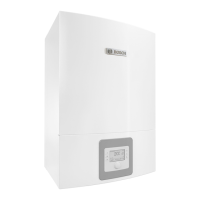
Details supplied parts, product information, overview, dimensions, and clearances of the indoor unit.
Covers the declaration of conformity and the type plate information for product identification.
Guides assembly of the indoor unit and explains minimum system volume needs for optimal heat pump operation.
Covers transport, storage, unpacking, and a checklist of recommended installation steps.
Details connecting the unit to the heat pump, heating system, and filling/venting procedures.
Covers electrical connections, fuse sizes, power limitations, and external inputs.
Details terminal connections for various sensors, pumps, valves, and communication modules on the installation module.
Illustrates different wiring configurations (star, serial) for connecting EMS bus modules.
Covers venting procedures, adjusting operating pressure, and pressure switch functions for system protection.
Details functional tests, individual operation, temperature checks, and overheating protection.
Instructions for cleaning the particle filter to prevent blockages and maintain system performance.
Steps for safely replacing components, including draining and refilling the system if necessary.
Guidelines for connecting accessories to the EMS-BUS, including spacing, cabling, and configuration.
Details external connections, maximum load for relay outputs, and sensor limit requirements.
Advice on installing DHW cylinders, particularly regarding natural circulation and heat loss, and the use of non-return valves.
Instructions for connecting the DHW cylinder temperature sensor (TW1) to the installation module.
Details the connection of the diverter valve (VW1) for domestic hot water cylinders and its operation modes.
Mentions the availability of a DHW cylinder for solar thermal heating and refers to separate instructions.
Guides on installing and configuring the Bosch CR10H room controller as a primary control unit.
Explains the need for a heating circuit module to control multiple heating circuits and their configuration.
Notes the connection of the DHW circulation pump (PW2) and its settings on the control unit.
Provides installation guidance for swimming pool mixers and modules, cautioning against incorrect placement.
Explains the function and installation of a 3-way valve (VCO) for buffer cylinders to short-circuit the hydraulic system.
Identifies the IP module and its connection port (RJ45).
Lists technical specifications for the indoor unit, including power supply, heater capacity, connections, and dimensions.
Explains hydraulic configurations, system solutions, and provides diagrams for various heat pump setups.
Covers CAN-BUS/EMS-BUS overview, single/three-phase heat pump wiring, module diagrams, sensor measurements, and cable details.
A comprehensive checklist for documenting the installation and commissioning process, covering system components, clearances, electrical, and power supply checks.
Provides fields for recording details of service and interim work, including engineer, company, and inhibitor concentration checks.

