Technical information
31
AWE – 6721835317 (2021/09)
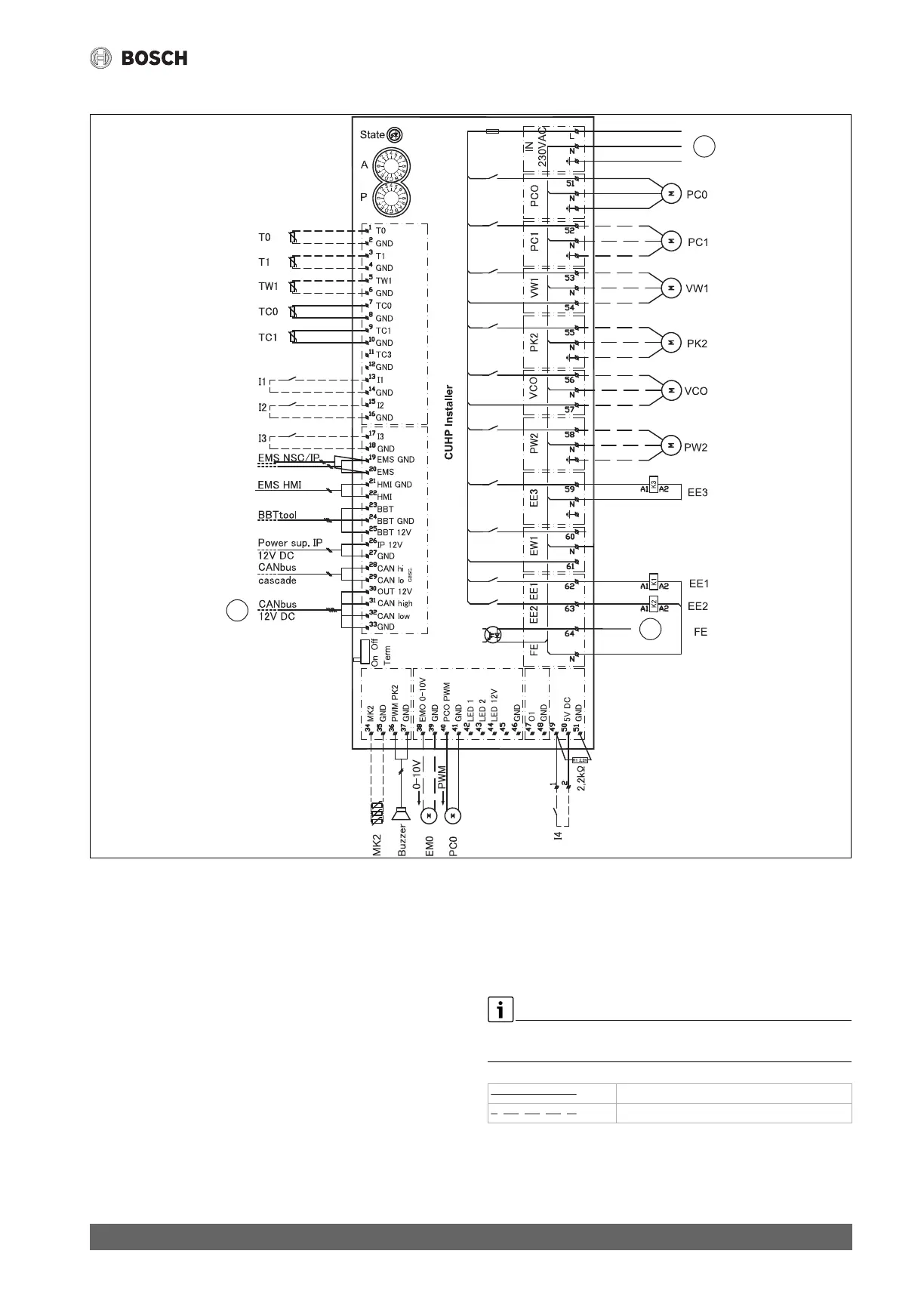
11.3.4 Wiring diagram of installation module with integrated electric booster heater
Fig. 34 Wiring diagram of installation module with integrated electric booster heater
[l1] External input 1
[l2] External input 2
[l3] External input 3
[l4] External input 4
[MK2/MD1]Humidity sensor
[Buzzer] Alarm buzzer (accessory)
[T0] Flow temperature sensor
[T1] Outdoor sensor
[TW1] Hot water temperature sensor
[TC0] Return heat transfer medium temperature sensor
[TC1] Temperature sensor for heat transfer medium flow
[F50] Fuse 6.3 A
[PC0] Pump PWM signal
[PC0] Heating pump
[PC1] Pump of heating system
[PK2] Cooling/fan convector relay output
[PW2] Hot water DHW circulation pump
[VC0] Circulation diverter valve, 230 V output
[VW1] Heating / DHW exchange valve
[EE1] Electric heater, step 1
[EE2] Electric heater, step 2
[EE3] Electric heater, step 3
[1] CAN-BUS for heat pump (I/O-module)
[2] FE, alarm of pressure switch, 230 V input
[3] Operating voltage, 230 V~
Maximum load at relay output: 2 A, cos> 0.4 In case of a higher load,
install an intermediate relay.
Factory connection
Connected during installation / accessories