Technical information
33
AWE – 6721835317 (2021/09)
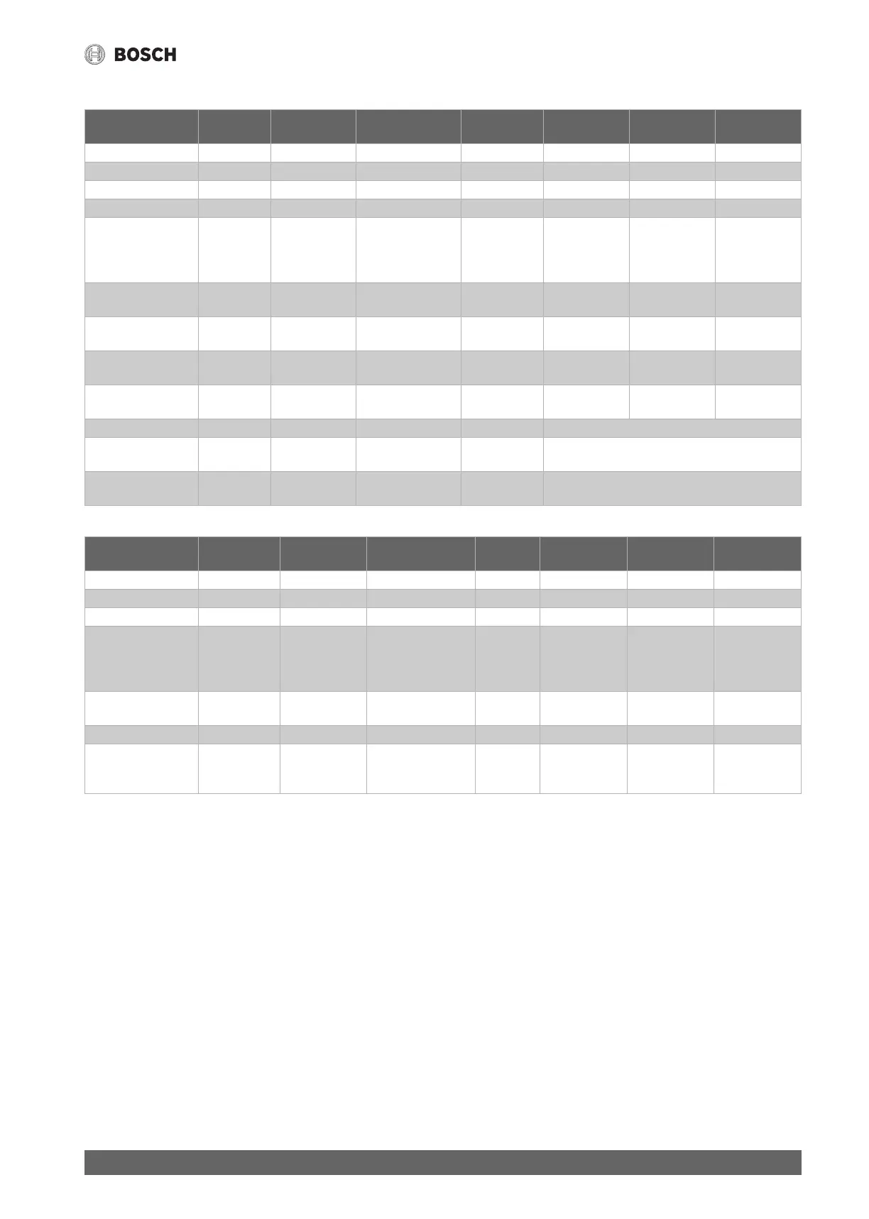
11.3.7 Cable diagram
Table 13 Connection to indoor units IDU AWE/AWB/AWM and AWMS
Table 14 Cable diagram, sensor
Description Min. cross-
section
Type of cable Max. length Connect to Connect to
terminal
Voltage source
Diverter valve VW1 3 x 1.5 mm² Integrated cable Indoor Unit 53 / 54 / N IDU
Diverter valve VC0 3 x 1.5 mm² Integrated cable Indoor Unit 56 / 57 / N IDU
Pump HC 1 PC1 3 x 1.5 mm² PVC hose line Indoor Unit 52 / N / PE
Circulating pump PW2 3 x 1.5 mm² PVC hose line 58 / N / 58
Connecting cable IDU -
ODU
CAN-BUS 2 x 2 x
0.75 mm
2
LIYCY (TP) 30 m 30(12V)
31(H)
32(L)
33(GND)
IDU
Power infeed IDU AWE/
AWM/AWMS
5 x 2.5 mm² Sub-distribution
3 x C16
Power infeed IDU AWB 3 x 1.5 mm² L / N SL Sub-distribution
1x C16
EMS - Modules SM100,
MM100...
0.5 mm² J-Y (ST)Y 2 x 2 x 0.6 100 m Indoor Unit 19 / 20
0-10 V actuation,
boiler
EM0 2 x 2 x
0.75 mm
2
LIYCY (TP) Indoor Unit 38 / 39 Basic controller,
boiler
PV function 0.4 mm² J-Y (ST)Y 2 x 2 x 0.6 From inverter to terminal I2 or I3 of the IDU
Smart Grid 0.4 mm² J-Y (ST)Y 2 x 2 x 0.6 From ripple control receiver to contact I4, terminal
49, 50 of the IDU
Energy supplier
blocking signal
Screened
cable
3 x 1.5 mm² PVC hose line From ripple control receiver to contact I1, terminal
13, 14 of the IDU
Sensors Description Min. cross-
section
Type of cable Max.
length
Connect to Connect to
terminal
Voltage source
Outdoors T1 0.5 mm
2
J-Y (ST)Y 2 x 2 x 0.6 Indoor Unit 3 / 4
Flow T0 0.5 mm
2
J-Y (ST)Y 2 x 2 x 0.6 Indoor Unit 1 / 2
Hot water TW1 0.5 mm
2
J-Y (ST)Y 2 x 2 x 0.6 Indoor Unit 5 / 6
Heat source TL2 Cable with plug Indoor unit,
cable with
mating
connector
Condensation point
sensor
MK2 (max. 5x) 0.5 mm
2
Integrated cable Indoor Unit 34 / 35
Sensor HC with mixer TC1 0.5 mm
2
J-Y (ST)Y 2 x 2 x 0.6 100 m MM100 1 / 2
Sensor, swimming
pool temperature
sensor
TC1 0.5 mm
2
J-Y (ST)Y 2 x 2 x 0.6 100 m MP100 1 / 2