Operation
AWE – 6721835317 (2021/09)
18
▶ Calculate the difference TC3–TC0.
▶ Check whether the difference corresponds to the delta value set for
heating mode.
If the temperature differential is too large:
▶ Vent the heating system.
▶ Clean filters / strainers.
▶ Check pipe dimensions.
Temperature differential in the heating system
▶ Set the output at the heating pump PC1 so that the following
difference is achieved:
▶ With underfloor heating system: 5 K.
▶ With radiators: 8 K.
7Operation
WARNING
Material damage from frost!
The heating or auxiliary heater may be irreparably damaged by frost.
▶ Do not start the indoor unit if there is a possibility of the heating or
auxiliary heater being frozen.
8 Maintenance
DANGER
Electrical shock!
▶ Before working on the electrics, the main power supply must be
switched off.
DANGER
Risk of electric shock!
Opening the installer module may cause injury by electric shock.
▶ Do not open the installer module to replace a component. If the
installer board or one of its components need to be replaced, remove
the installer module completely and replace by a new one.
NOTICE
Deformation due to heat!
If the temperature is too high, the insulation (EPP) in the indoor unit
deforms.
▶ When carrying out brazing work in the heat pump, protect the
insulation with a heat resistant cloth or damp cloth.
▶ Only use original spare parts!
▶ Refer to the spare parts list when ordering spare parts.
▶Replace removed gaskets and O-rings with new ones.
The tasks described below must be carried out during an inspection.
Display activated alarm
▶ Check the alarm log (instructions for the control device).
Function test
▶ Carry out function check ( Chap. 6.4).
8.1 Particle filter
The filter prevents particles and contamination from entering the heat
pump. Over time, the filter can become blocked and must be cleaned.
To clean the filter, the system does not need to be emptied. The filter and
shut-off valve are integrated.
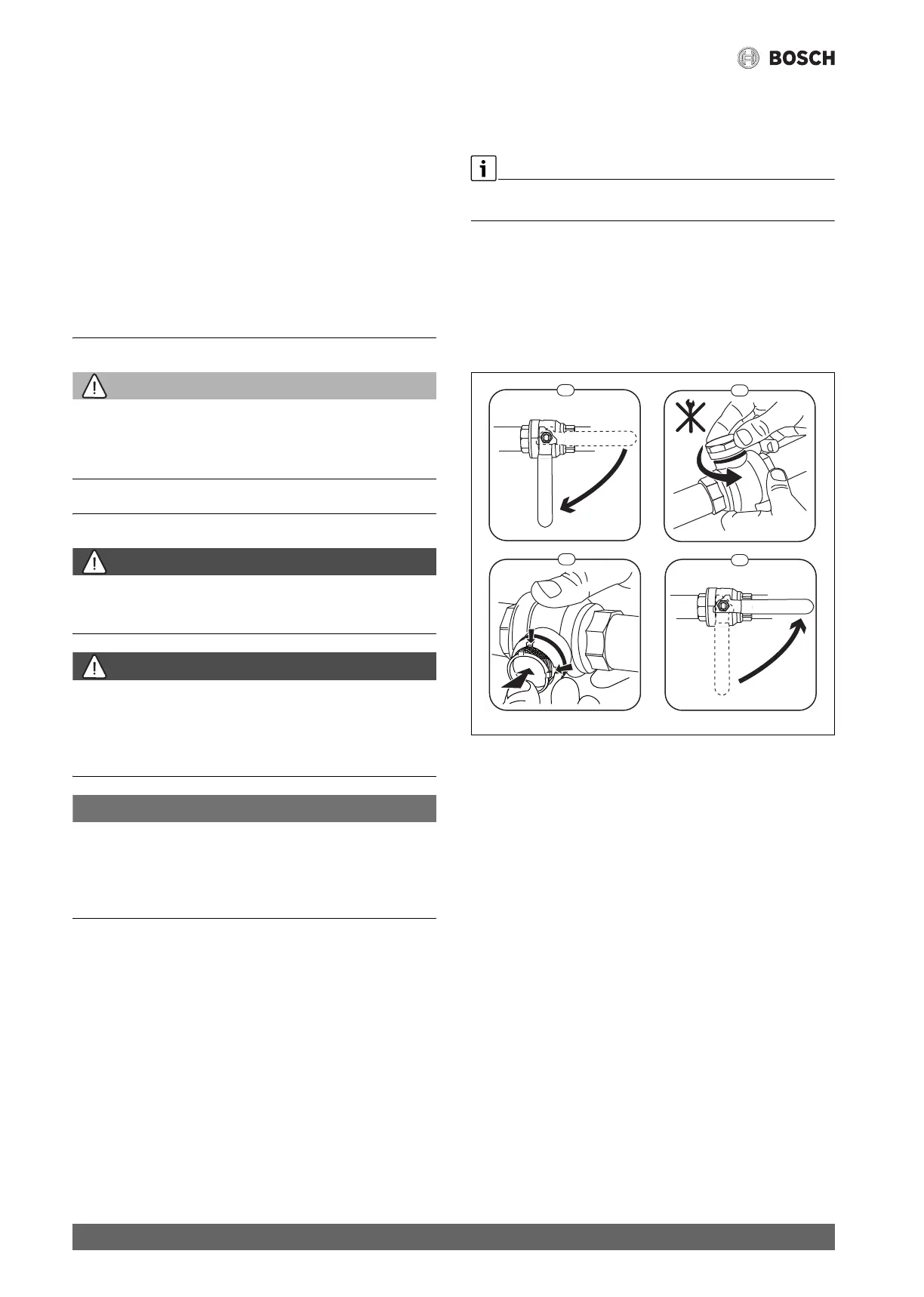
Cleaning the strainer
▶ Close the valve (1).
▶ Unscrew the cap (manually) (2).
▶ Take out the strainer and clean it by running water over it or by
pressure cleaning.
▶ Reinstall the strainer. For proper assembly, make sure that the guide
bumps fit into the recesses in the valve.
Fig. 16 Cleaning the strainer
▶ Screw the cap back on (tighten handtight).
▶ Open the valve (4).
Check the magnetite indicator
After installation and startup the magnetite indicator must be checked at
more frequent intervals. If a lot of magnetic dirt is clinging to the
magnetic bar in the particulate filter and that dirt frequently causes an
alarm related to the poor flow (e.g., low or poor flow, high flow supply or
HP alarm) an approved magnetite filter must be installed to avoid regular
draining of the indicator. The magnetic filter must be installed in addition
to the mesh filter and be placed in the secondary circuit after the
hydraulic separation. A filter also increases the longevity of components
in the heat pump as well as the remaining parts of the heating system.
When installing a magnetic filter, consideration should be made for the
product specific impact on the pressure drop on the system.
8.2 Replacing components
If you intend to replace a component and the indoor unit needs to be
emptied and refilled to do this, carry out the following steps:
1. De-energise the heat pump and indoor unit.
2. Make sure that that automatic air vent valve VL1 is open.
3. Close the valves to the heating system; particle filter SC1 and VC3.
4. Connect a hose to the drain valve VA0 and route the other end to a
drain. Open the valve.
5. Wait until no more water flows into the drain.
6. Replace components.
1.
2.
2.
1.
1
2
3
4
6 720 805 915-01.1I