Technical information
AWE – 6721835317 (2021/09)
24
11.2 Hydraulic configuration
The product must only be installed according to the manufacturer's
official system solutions. Other system solutions are not permitted.
Liability is voided in the case of damage and problems resulting from
impermissible installation.
Certain system solutions require accessories (buffer cylinder, diverter
valve, mixer, heating pump). The heating pump PC1 is activated by the
controller in the indoor unit.
When a freshwater station is installed, it must have its own control.
If a buffer cylinder is used, the diverter valve VC0 must be installed in
accordance with the system solution.
11.2.1 Explanations of the system solutions
11.2.2 Bypass for the heating system
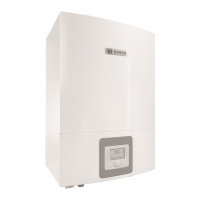
Fig. 27 Indoor unit with heating circuit and bypass
[1] Bypass
[2] Flow
[3] Return
If no buffer cylinder is installed, a bypass is required. The bypass must be
at least 10 times longer than the internal pipe diameter.
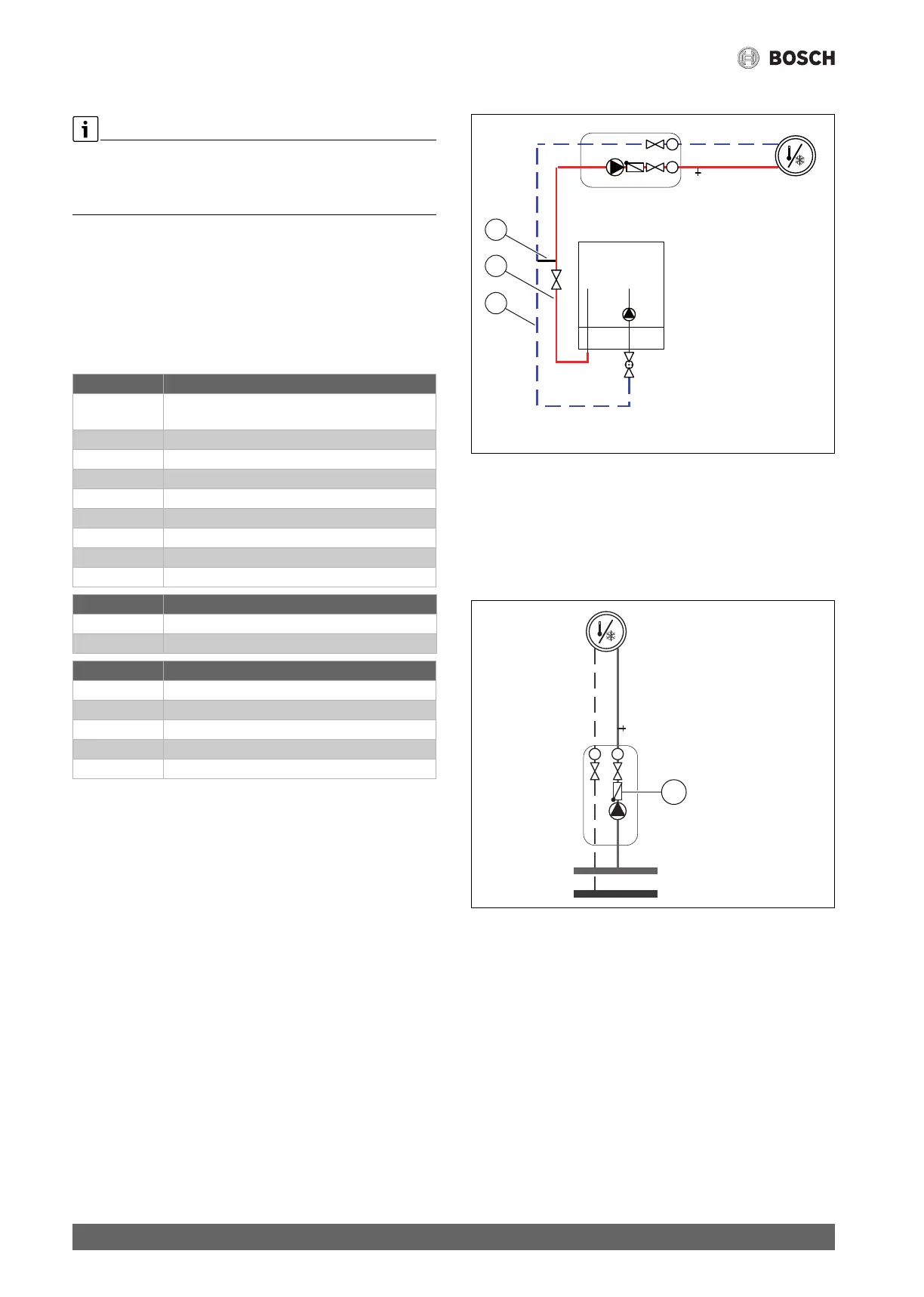
11.2.3 Non-return valve in the heating circuit
Fig. 28 Heat. circ.
[1] Non return valve
A non-return valve is required in each heating circuit to prevent natural
circulation in summer mode. Natural circulation can occur if the diverter
valve of the DHW line is open in the direction of the heating system
during DHW heating.
General
SEC 20 Installation module integrated in the heat pump
module
HPC410 Control unit
CR10H Room controller (accessories)
T1 Outdoor sensor
MK2 Humidity sensor (accessory)
CC1 DHW cylinder (accessory)
VW1 Diverter valve (accessory)
PW2 DHW circulation pump (accessory)
TW1 Hot water temperature sensor
Heating circuit without mixer
PC1 Circulation pump, heating circuit
T0 Flow temperature sensor
Heating circuit with mixer
MM100 Heating circuit module (control unit for circuit)
PC1 Pump for heating circuit 2
VC1 Mixer
TC1 Flow temperature sensor, heating circuit 2, 3 ...
MC1 Thermal shut-off valve, heating circuit 2, 3 ...
T
T
1
0010019882-002