Notice!
Use either the terminal strip wiring or interconnect cable to wire to the control panel. Do not
use both. When connecting multiple modules, you can combine terminal strip and
interconnect wiring connectors to daisy-chain the modules in series.
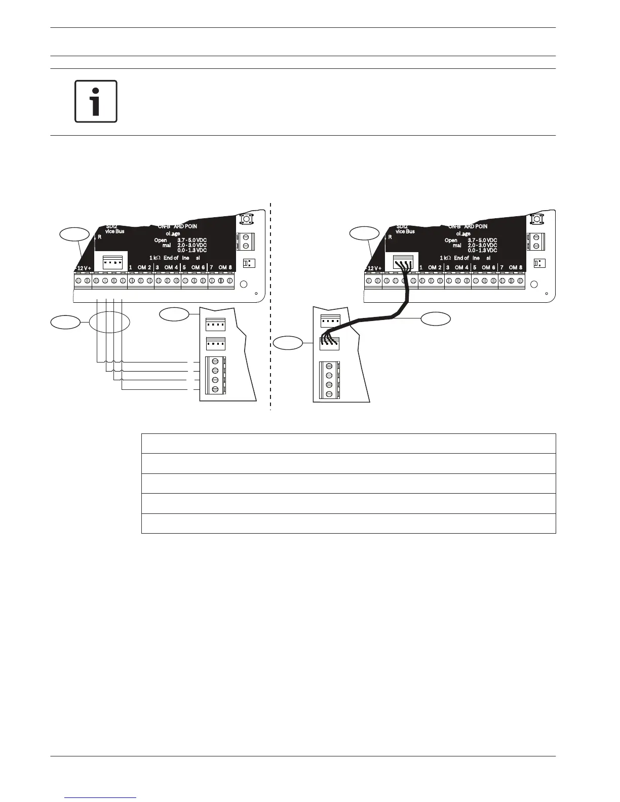
Wire to an SDI2 control panel
Run the wiring connections from the module to the data bus terminals on the compatible
control panel.
R
Y
G
B
R
Y
G
B
3.7 - 5.0 VDC
2.0 - 3.0 VDC
0.0 - 1.3 VDC
Open
Normal
Short
3
R
Y
G
B
1
1
2
4
2
7 COM 8
C
OUTPUT
B
1 k End of Line Resistors
Voltage Ranges
ON-BOARD POINTS
3 COM 4 5 COM 61 COM 2
R Y G B
SDI2
Device Bus
AUX
- 12 V +
7 COM 8
C
OUTPUT
B
1 k End of Line Resistors
Voltage Ranges
ON-BOARD POINTS
3.7 - 5.0 VDC
2.0 - 3.0 VDC
0.0 - 1.3 VDC
Open
Normal
Short
3 COM 4 5 COM 61 COM 2
R Y G B
SDI2
Device Bus
AUX
- 12 V +
TMPR
1 COM 2 7 COM 83 COM 4 5 COM 6
RESET
COM AUX R Y G B
PWR A B COM
B C
OUTPUT
TMPR
1 COM 2 7 COM 83 COM 4 5 COM 6
RESET
COM AUX R Y G B
PWR A B COM
B C
OUTPUT
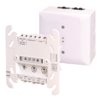
Figure 4.5: Using terminal strip or interconnect cable wiring on an SDI2 control panel (B Series control panel shown)
Callout ᅳ Description
1 ᅳ Compatible SDI2 control panel (B Series control panel shown)
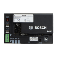
2 ᅳ B450
3 ᅳ Terminal strip wiring
4 ᅳ Interconnect cable
4.5.1
14 en | Installation
Conettix Plug-in Communicator
Interface
2013.09 | 02 | F.01U.282.875 Installation and Operation Guide Bosch Security Systems, Inc.