English–14
3 609 929 A44 • (05.09) T
LED Indicators
Battery Condition Indicator
If the charging of the battery 18 is neces-
sary, the LED indicator 11 blinks green.
You can still use the power tool for approx.
6–8 screw fasteners.
If the LED indicator lights red, the capacity is no long-
er adequate for another screwing fastener. The pow-
er tool can no longer be switched on. The switch-on
lock remains active until a charged battery is inserted.
A considerably shortened operating time of the pow-
er tool after each charging indicates that the battery
must be replaced soon. Dispose of the used battery
in accordance with the legal/country-specific regula-
tions.
Note: If, instead of the rechargeable battery 18, a
voltage adapter and the constant voltage regulator
4EXACT are used, the LED indicator 11 has no func-
tion.
Screwing Fastener Indicator
When the preset torque is reached, the
switch-off coupling responds. The LED in-
dicator 9 lights green.
If the preset torque is not reached, the LED indicator
9 lights red and an acoustical signal sounds. The
screwing fastener must be performed again.
Bluetooth
®
Connection Indicator
Press the on/off switch 12 in order to activate the
Bluetooth
®
connection. The red LED indicator 10
blinks as long as the screw driver searches for a con-
nection.
A red light of the LED indicator 10 that lights contin-
uously shows that the Bluetooth
®
connection has
been made. The screwdriver is still locked, however.
If the driver is released by access point EXAConnecT,
the LED indicator 10 goes out.
If the LED indicator 10 blinks only briefly after the
on/off switch is pressed and then goes out, the pow-
er supply of the driver is no longer adequate for a
screwing fastener.
Repeat Protection
When the switch-off coupling responds for a screw-
ing fastener, the motor switches off. Switching on
again is possible only after a 0.7 second delay. In this
manner, an unintentional re-tightening of an already
seated screw is avoided.
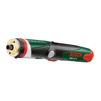
Adjusting the Angled Drive Head
The angled drive head 3 can be adjusted to a total of
eight positions.
Hold the machine with the open-ended spanner 6 on
the spanner flats 5 of the angled head flange.
Never clamp the machine on the housing shells.
Loosen with the open-ended spanner 4 on the span-
ner flats 16 of the nut sleeve. Adjust the angled drive
head 3 in 45° steps to the desired position and
retighten with the open-ended spanner 4 on the
spanner flats 16 of the sleeve nut. Hold the angled
head flange with the open-ended spanner 6 to pre-
vent turning.
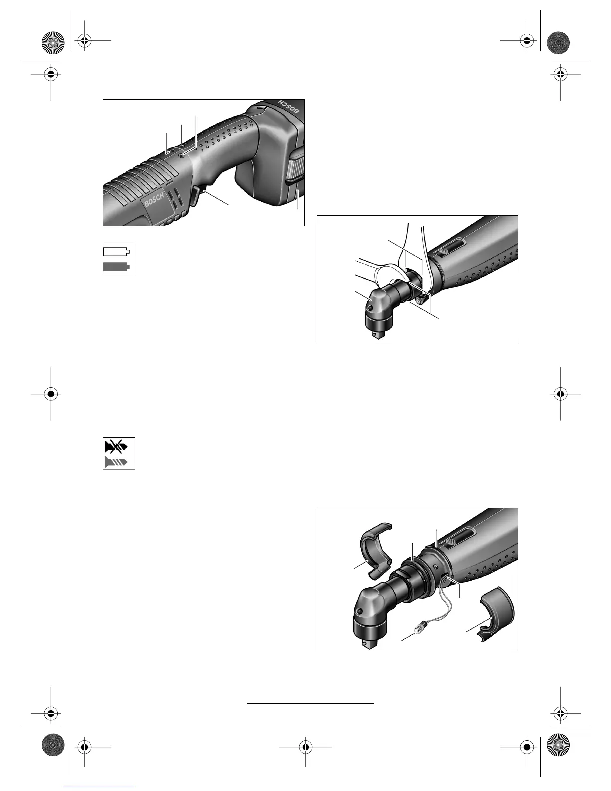
Adjusting the LED Working Position
Press off the marking ring 19 with a thin screwdriver
blade, a knife, or similar. Slide the spring ring 30 with
spring ring pliers to the rear onto the housing shell.
The two shell halves of the LED holder 15 that en-
9
11
10
12
18
Type 0 602 491 647/... 650/... 651/... 652/... 656/
... 669/... 671/... 673/... 675
Type 0 602 491 647/... 650/... 651/... 652/... 656/
... 669/... 671/... 673/... 675
5
6
4
3
16
19
15
30
31
15
26
BTEXACT_bu_3609929A44_t.fm Seite 14 Montag, 5. September 2005 2:12 14