Thermostat Connections | 9CE Series Heat Pump
6 720 220 048 (2014/08)CE Series Heat Pump
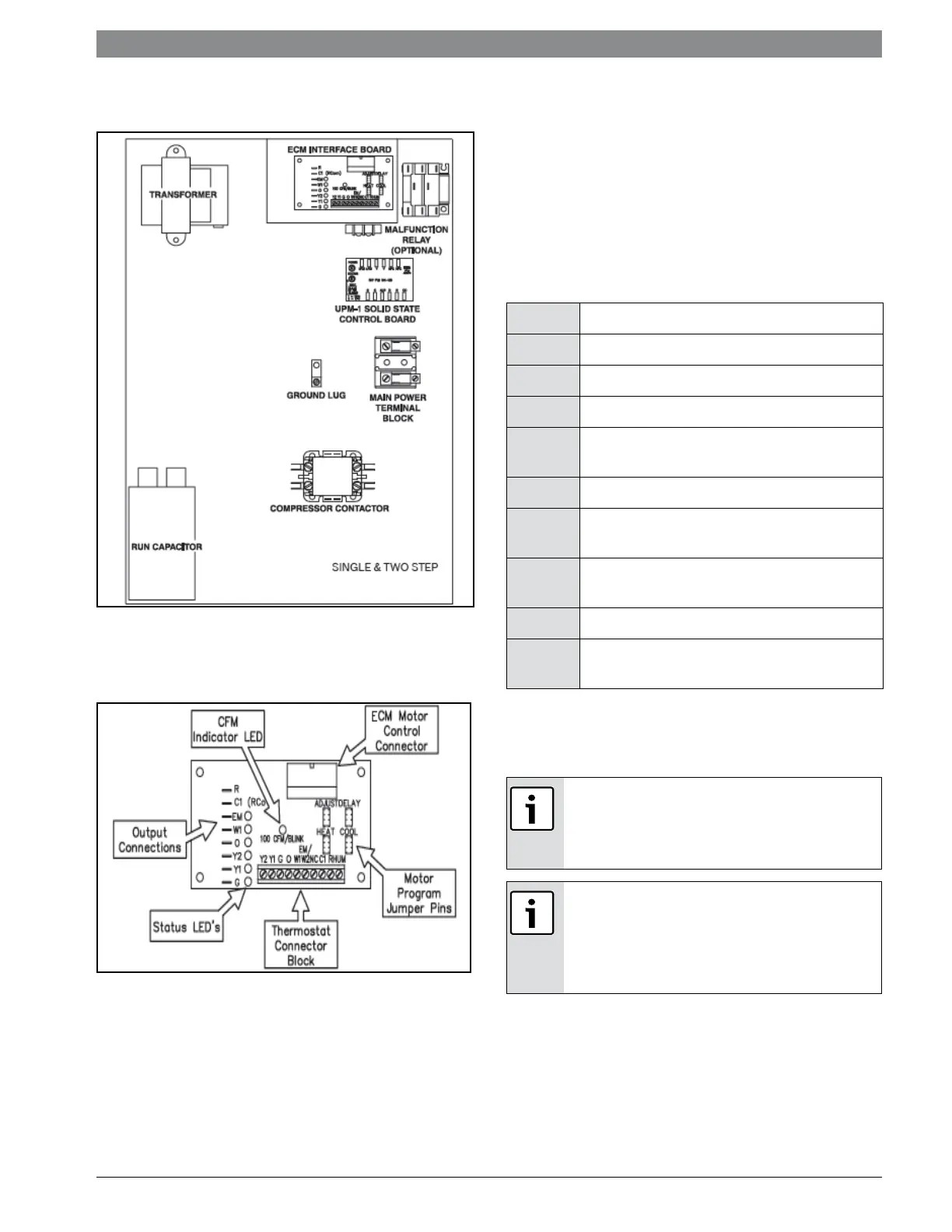
Figure # 10
ECM INTERFACE BOARD
Figure # 11
THERMOSTAT CONNECTIONS
Thermostat wiring is connected to the 10 pin
screw type terminal block on the lower center
portion of the ECM Interface Board. In addition to
providing a connecting point for thermostat wiring,
the interface board also translates thermostat
inputs into control commands for the Electronic
Commutated Motor (ECM) DC fan motor and
displays an LED indication of operating status. The
thermostat connections and their functions are as
follows:
If the unit is being connected to a thermostat with
a malfunction light, this connection is made at the
unit malfunction output or relay.
To the left of the thermostat connection block are
a row of 2 red and 4 green LED’s. These LED’s
indicate the operating status of the unit. They are
labeled as follows:
Y1 First Stage Compressor Operation
Y2 Second Stage Compressor Operation
G Fan
O Reversing Valve (energized in cooling)
W1 Auxiliary Electric Heat (runs in
conjunction with compressor)
EM/W2 Emergency Heat (electric heat only)
NC Transformer 24 VAC Common (extra
connection)
C1 Transformer 24 VAC Common
(primary connection)
R Transformer 24 VAC Hot
HUM Dehumidification Mode (not used in
CE Series)
If the thermostat is provided with a malfunction
light powered off of the common (C) side of the
transformer, a jumper between “R” and “COM”
terminal of the “ALR” contacts must be made.
If the thermostat is provided with a malfunction
light powered off of the hot (R) side of the
transformer, then the thermostat malfunction
light should be connected directly to the (ALR)
contact on the unit’s UPM board.
 Loading...


