SERVICE MANUAL
Climate Class 6100i / 6000i / 8100i / 8000i
S1101AYXP9YMBT
CONTENTS
Parts marked with "
!
" are important for maintaining the safety of the set. Be sure to replace these parts with specied ones for maintaining the safety
and performance of the set.
This document has been published to be used for
after sales service only.
The contents are subject to change without notice.
CHAPTER 1. PRODUCT SPECIFICATION
[1] SPECIFICATION ...............................................1-1
[2] EXTERNAL DIMENSION ..................................1-5
[3] WIRING DIAGRAM ...........................................1-7
[4] ELECTRICAL PARTS ........................................ 1-8
CHAPTER 2. EXPLANATION OF CIRCUIT AND
OPERATION
[1] BLOCK DIAGRAMS ..........................................2-1
[2] MICROCOMPUTER CONTROL SYSTEM ........2-3
CHAPTER 3. FUNCTION
[1] FUNCTION ........................................................3-1
[2] PAM Circuit ........................................................ 3-3
[3] IPM Drive Circuit ................................................3-5
[4] 180deg. Energizing Control ...............................3-6
CHAPTER 4. FUNCTION AND OPERATION OF
PROTECTIVE PROCEDURES
[1] PROTECTION DEVICE FUNCTIONS AND
OPERATIONS ....................................................4-1
[2] AIR CONDITIONER OPERATION IN
THERMISTOR ERROR .....................................4-3
[3] THERMISTOR TEMPERATURE
CHARACTERISTICS ........................................4-5
[4] HOW TO OPERATE THE OUTDOOR UNIT
INDEPENDENTLY .............................................4-6
[5] GENERAL TROUBLESHOOTING CHART .......4-6
[6] MALFUNCTION (PARTS) CHECK METHOD ...4-8
[7] OUTDOOR UNIT CHECK METHOD .................4-11
[8] TROUBLESHOOTING GUIDE ..........................4-13
CHAPTER 5. REFRIGERATION CYCLE
[1] SCHEMATIC DIAGRAM .................................... 5-1
[2] STANDARD CONDITION .................................. 5-1
[3] TEMPERATURE AT EACH PART AND
PRESSURE IN 3-WAY VALVE ...........................5-1
[4] PERFORMANCE CURVES ...............................5-3
CHAPTER 6. DISASSEMBLY PROCEDURE
[1] INDOOR UNIT ...................................................6-1
[2] OUTDOOR UNIT
(CLC6101i 50/65 HE, CLC6001i 25/35 E) ......... 6-7
[3] OUTDOOR UNIT
(CLC8101i 65 HE, CLC8001i 25/35 E) .............. 6-11
PARTS LIST
FAILURE DIAGNOSIS FLOWCHART
In the interests of user-safety (Required by safety regulations in some countries) the set should be re-
stored to its original condition and only parts identical to those specied should be used.
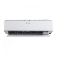
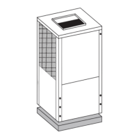
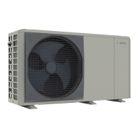
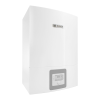
INDOOR UNIT OUTDOOR UNIT
CLC6101i-W 50 HE CLC6101i 50 HE
CLC6101i-W 65 HE CLC6101i 65 HE
CLC8101i-W 65 HE(T/S/R) CLC8101i 65 HE
CLC6001i-W 25 E CLC6001i 25 E
CLC6001i-W 35 E CLC6001i 35 E
CLC8001i-W 25 E(T/S/R) CLC8001i 25 E
CLC8001i-W 35 E(T/S/R) CLC8001i 35 E
AIR/AIR HEAT PUMP
MODELS
"Vertical louver (V-louver)" in this document means "horizontal air ow louver" in the operation manual.
"Horizontal louver (H-louver)" in this document means "vertical air ow louver" in the operation manual.


