16 en | Wiring Long-range beam smoke detectors
2017.03 | 7.0 | F.01U.068.899 Installation manual Bosch Security Systems, Inc.
5 Wiring
Warning!
Only apply power after all connections are made and inspected.
Notice!
Do not install on fire circuits programmed for alarm verification.
Notice!
Do not coil excess wiring inside the units.
5.1 Wiring a single detector
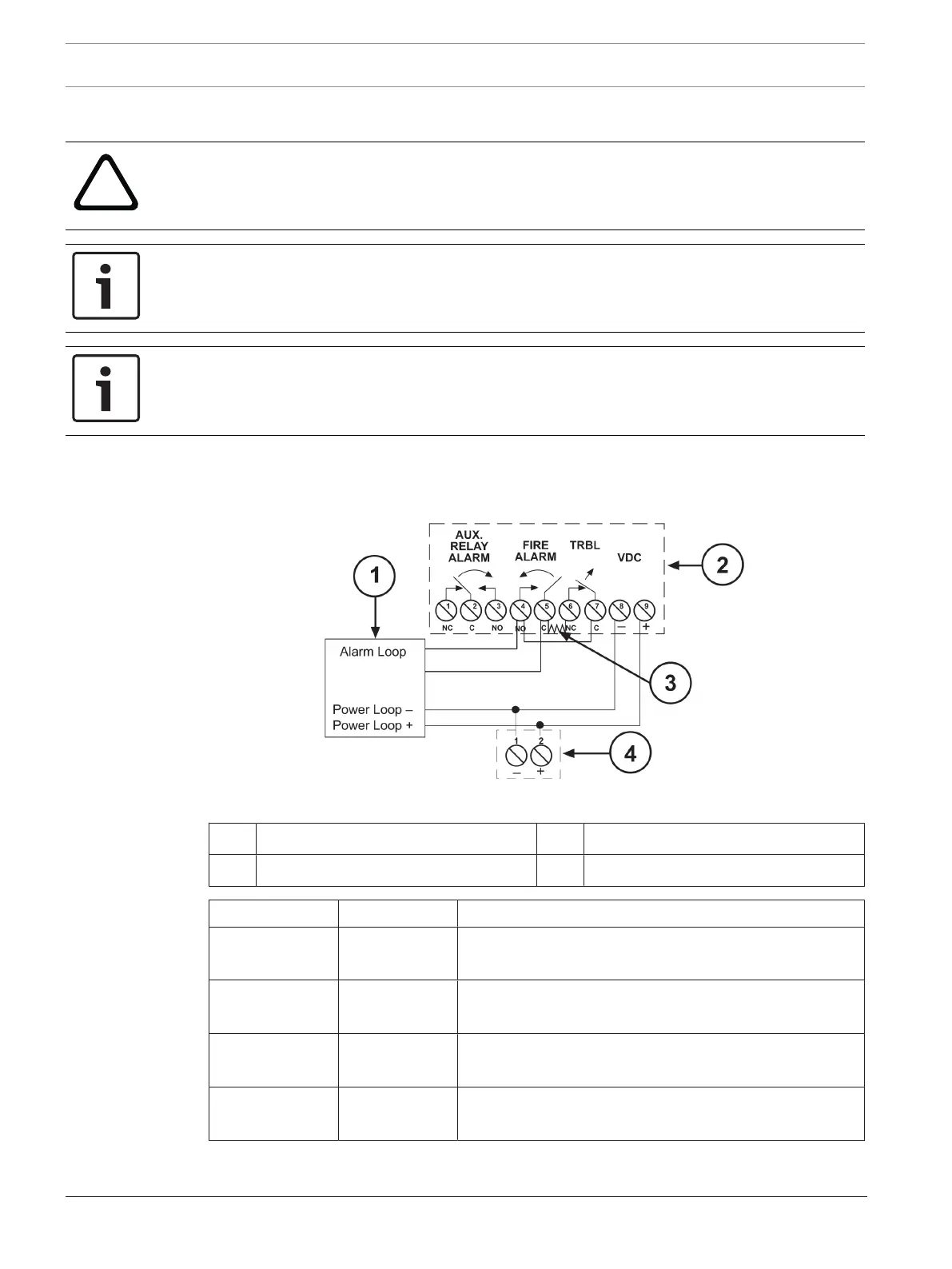
When wiring the transmitter and receiver terminals, see the following figure and table.
Figure5.1: Wiring a single detector
1 Fire alarm control panel (FACP) 3 End-of-line (EOL) resistor
2 Receiver 4 Transmitter
Type Terminal Description
Transmitter
terminals
1 and 2 Input power terminals. for operating voltages, see
Specifications, page 29.
Receiver
terminals
1, 2, and 3 Form C auxiliary relay contacts. On fire alarm, Terminals
1 and 2 open, Terminals 2 and 3 close (short).
Receiver
terminals
4 and 5 On fire alarm, normally open (NO) fire alarm contacts
close (short).
Receiver
terminals
6 and 7 On trouble, normally closed (NC) trouble contacts open.