18 en | Wiring Long-range beam smoke detectors
2017.03 | 7.0 | F.01U.068.899 Installation manual Bosch Security Systems, Inc.
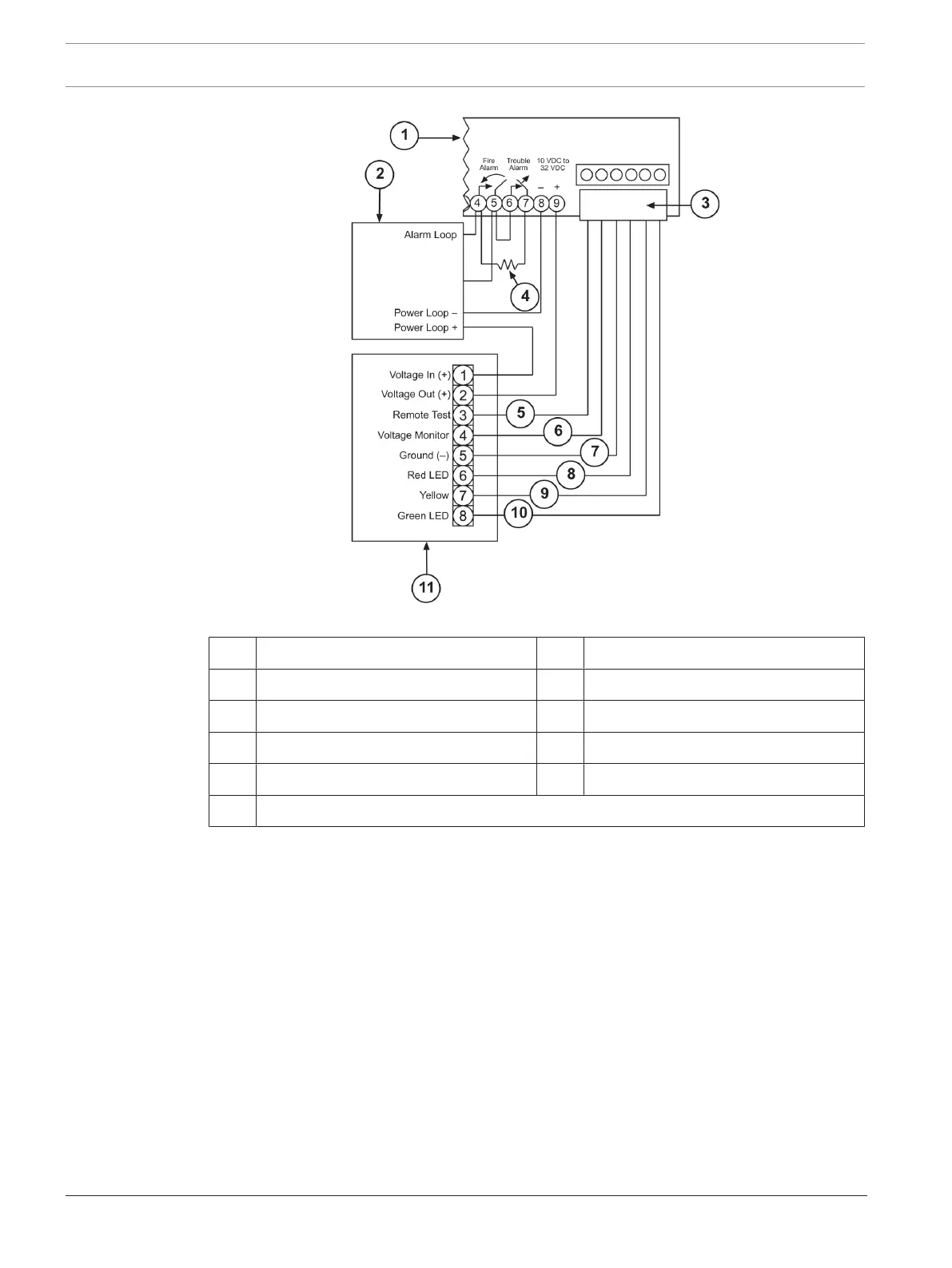
Figure5.3: Connecting a D344-RT Remote Test and Indicator Plate
1 D296/D297 receiver 2 Fire alarm control panel (FACP)
3 Remote indicator plate connector 4 End-of-line resistor
5 Remote test (orange wire) 6 Voltage monitor (blue wire)
7 Ground (black wire) 8 Red LED (red wire)
9 Yellow LED (yellow wire) 10 Green LED (green wire)
11 D34-RT Remote Test and Indicator Plate
5.3 Wiring multiple detectors
For smooth, flat ceilings, mount the detectors so the spacing is ≤ 60ft. (18.3m) between
beam paths. Ensure that no more than half of this spacing is between the beam path and side
wall. (The side wall is the wall parallel to the beam path). Other spacing depends on ceiling
height, air flow characteristics, and response requirements. The minimum spacing between
alternated adjacent detectors is 1/10th the distance between the transmitter and receiver. For
example, if the beam length is 300ft. (91m), place detectors ≤ 30ft. (9.1m) apart. For layout
placement, see the following figure.