Long-range beam smoke detectors Wiring | en 17
Bosch Security Systems, Inc. Installation manual 2017.03 | 7.0 | F.01U.068.899
Type Terminal Description
Receiver
terminals
8 and 9 Input power terminals. For operating voltages, see
Specifications, page 29.
Tab.5.3: Transmitter and Receiver Terminals
Notice!
To reset after a fire alarm, interrupt power to the receiver for a minimum of 1sec. If the fire
panel does not allow you to reset, install a switch in series with Terminal 8.
5.2 Wiring a remote indicator
A D344‑RL Remote indicator plate is shipped with the D296 as a standard accessory. The
D344‑RL has three LEDs to indicate the detector’s condition and status. The indicator plate
also has test points for measuring the sensitivity voltage. Although not required, Bosch
recommends the D344-RL’s installation to check the detector’s condition from ground level. If
using D344‑RL, install the remote indicator connector to the receiver as indicated in the
following figure.
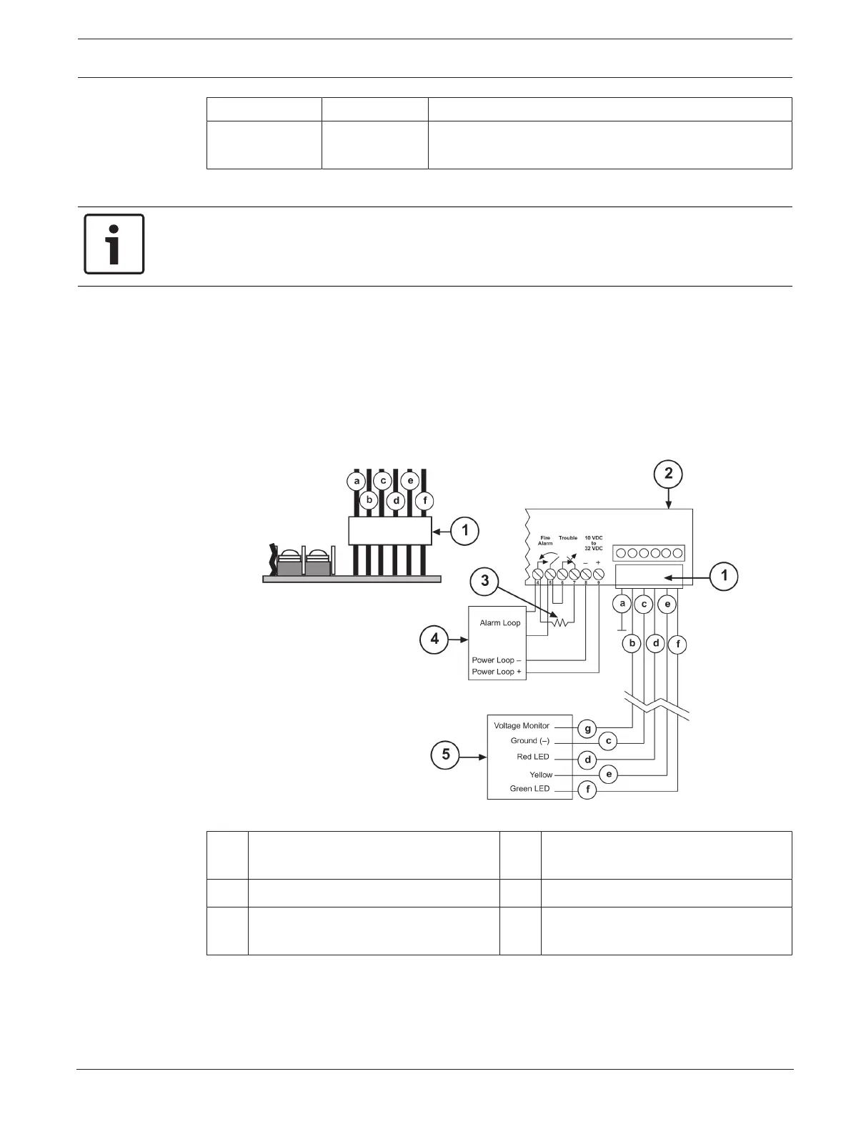
Figure5.2: Connecting a D344-RL Remote Indicator Plate
1 D344‑RL Remote Indicator Plate
Connector
4 FACP
2 D296/D297 Receiver 5 D344‑RL Remote Indicator Plate
3 EOL resistor 6 Wiring: a=orange, b=blue, c=black,
d=red, e=yellow, f=green, g=violet
You can wire the D344‑RL a maximum of 500ft. (152m) from the receiver.
A D344‑RT Remote test/indicator plate can be used if remote alarm testing is desired. Connect
the wiring between the D296 or D297 and a D344‑RT according to the following figure: