Long-range beam smoke detectors Setup | en 21
Bosch Security Systems, Inc. Installation manual 2017.03 | 7.0 | F.01U.068.899
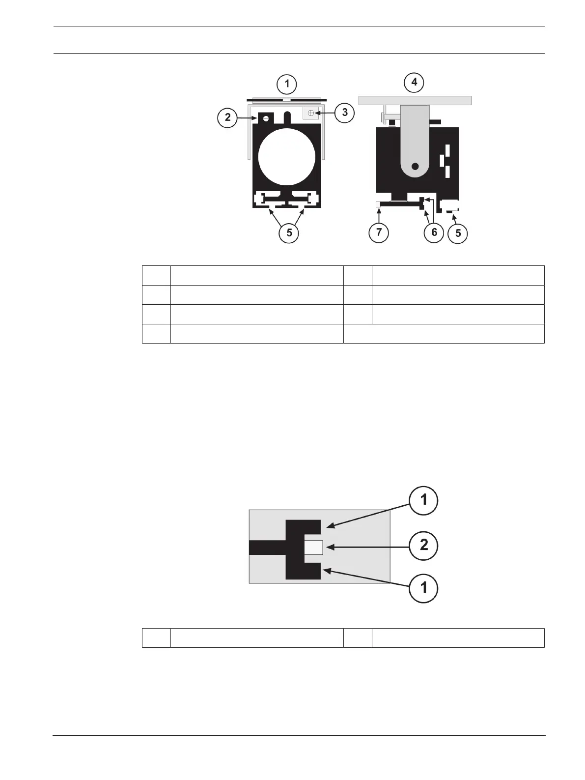
Figure6.3: Optical Module
1 Front view 5 Alignment mirrors (3)
2 Vertical fine tune 6 Rear bore sights (2)
3 Horizontal fine tune 7 Front bore sight
4 Side view
For preliminary alignment of the transmitter and receiver, use the following procedure:
1. Look into either mirror from a side angle at ≥ 2ft. (61cm) from the module.
2. Use the rear and front sights in the same way as you use sights when aiming a gun.
3. Rotate the transmitter's optical module left or right until you see the reflection in the
mirror of:
– aiming light image or
– receiver’s image, if the aiming light is not used
4. The optical module is aligned when the front bore sight is in the center of the rear bore
sights. See the following figure.
Figure6.4: Alignment Mirror
1 Rear bore sights (2) 2 Front bore sight
5. Adjust the optical module up or down until you see the image. Use the supplied Allen
wrench to adjust the Vertical Fine Tuning adjustment Allen screw.
6. Fine tune the image to the center of the mirror. It should be aligned with the front and
rear bore sights. Use the Horizontal and Vertical Fine Tuning adjustment screws for
tuning.