Long-range beam smoke detectors Setup | en 23
Bosch Security Systems, Inc. Installation manual 2017.03 | 7.0 | F.01U.068.899
– The maximum voltage peak reading varies, depending on the distance between the
transmitter and receiver. The acceptable peak voltage range is from 0.50V to 5.00V. The
voltage at the receiver is greater at shorter distances.
– Make a note of the alignment voltage. It might be helpful if you need to troubleshoot at
another time.
Notice!
Peak the voltage to ensure a stable and trouble-free detector.
5. After completing the fine-tune alignment, remove the test cable.
6. Replace and secure the receiver’s cover.
7. Check the status of the receiver’s green LED to ensure it is still flashing.
8. With the meter still connected to the test cable, reinstall this cable to P6. Route the test
cable through the opening in the cover (white lead towards center of the receiver).
9. At this point, you can perform an Alarm Test. Connect the D1005’s white and black wires.
Reset the receiver by temporarily removing power.
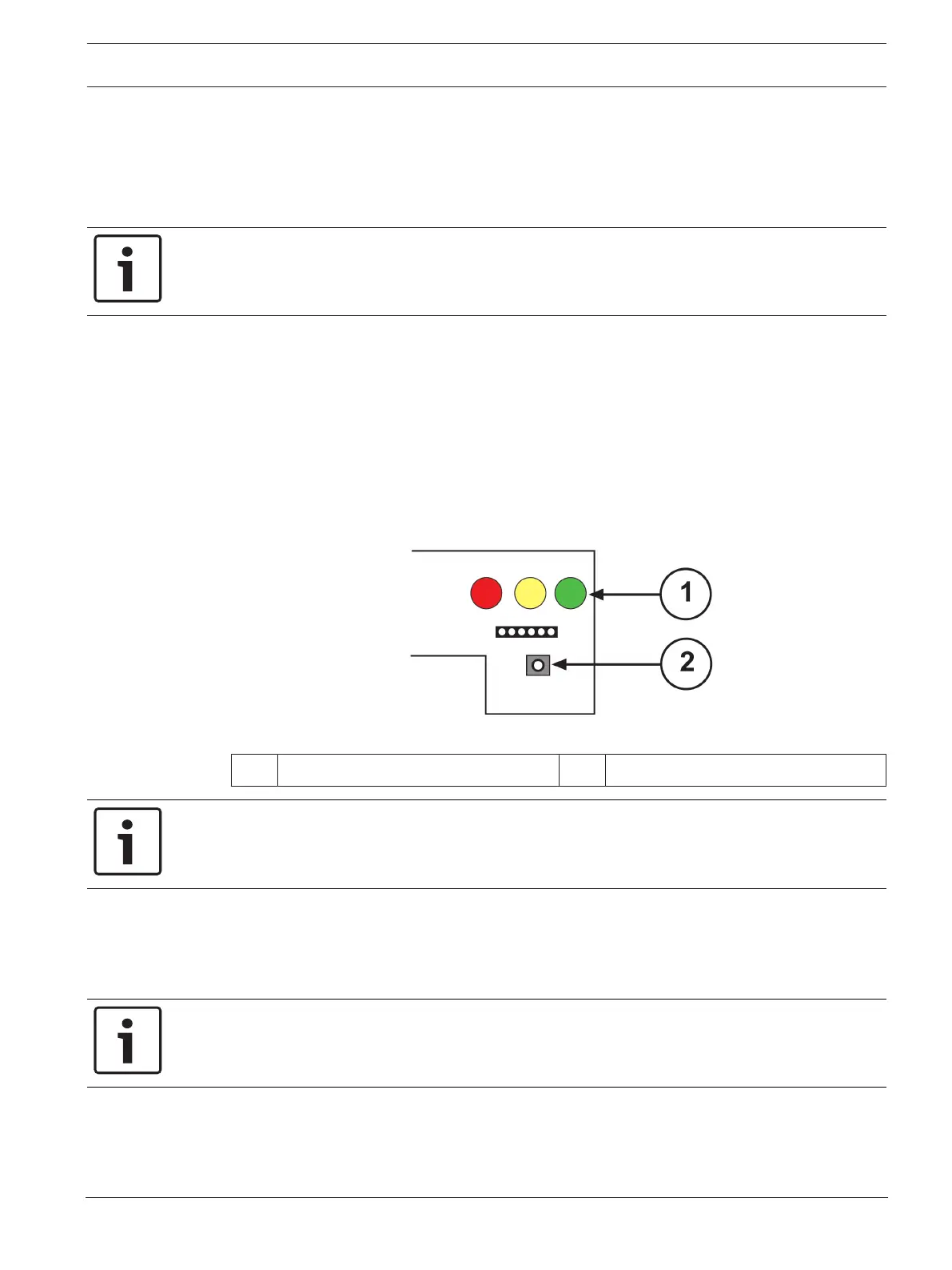
10. Press the receiver’s Setup button, located below the P6 and test cable connection. See
the following figure.
Figure6.6: Receiver Setup Button
1 LEDs 2 Setup button
Notice!
Only press the Setup button if the covers are on both the transmitter and receiver.
– A 1-min to 2-min automatic internal setup process begins. This setup ends in a reference
voltage that is used to measure beam blockages.
– The red and yellow LEDs turn off and the green LED turns steadily on. After some voltage
fluctuations, the meter sets to 5.0VDC.
Notice!
During this time, do not block the beam or move the units.
11. At the end of the setup, the receiver’s green LED flashes. The voltage decreases to a
range from 3.8VDC to 4.2VDC. Use this voltage as a reference when you compare later
readings to determine the need for cleaning. If the voltage is not within this range, press
the Setup button.