6 en | System Overview Conventional Fire Panel
F.01U.172.982 | 5.0 | 2012.04 Operation Guide Bosch Sicherheitssysteme GmbH
3 System Overview
3.1 Functionality
The FPC-500 Fire Panel is the main component of your fire
detection system. As the central control unit, the FPC-500
manages all information received from the detectors.
Depending on the relevant programming, the FPC-500 Fire
Panel relays all alarms to the connected notification appliances
and outputs.
As the user, you can control the behavior of the entire system.
You can silence and reset triggered alarms, change alarm
triggering delays (day/night mode), test zones and much more.
However, the system can only be programmed by persons with
advanced user rights. Therefore, any faults etc. must be
reported to your on-site specialist.
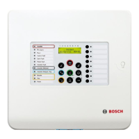
3.2 Display on Central Unit
Your fire panel features a number of LEDs to indicate operating
states and faults.
Zone LED Meaning
Red Constant The relevant zone is in alarm state.
Red Flashing, 0.5 Hz The zone has triggered a pre-alarm.
Yellow Flashing, 0.5 Hz The zone has a fault.
Yellow Constant The zone is deactivated.
Yellow Flashing, 2 Hz The zone is in test mode.
Notification appliance
fault/disabled – LED
Meaning
Yellow Constant Notification appliances are disabled.
Yellow Flashing, 2 Hz There is a fault in the notification appliance.