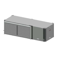
Vertical configurability | 23SM Series Heat Pump
6 720 220 406 (2013/1)SM Series Heat Pump
10. Route the Unit E-box to Electric Heat wiring
harness to the new Electric Heat Element
location.
11. Connect wiring harness to the connector on
the side of Electric Heat E-Box. (Figure#80)
Figure # 80
12. Reconnect high voltage wiring from Electric
Heat E-Box and Heating Element(s) matching
wire number to terminals as
shown.(Figure#81)
Figure # 81
13. Re-install Electric Heat Elements Cover(s).
(Figure#82)
Figure # 82
Electrical Box re-configuration
E-box is designed to be removable to support field
configuration of unit: Left-Hand Return (factory
default) and Right-Hand Return, and also to allow
full access to compressor during servicing.
The Electrical box (E-Box) has a set of plugs that
allows complete removal from the system while
keeping the majority of its internal connections.
(FIgure#120 & #121, Pg#67 and Pg#68)
1. Disconnect wiring harness by unplugging the
following plugs: P18, P19, P20 and P23 (P12 if
unit is equipped with Electric Heat).
(FIgure#120 & #121, Pg#67 and Pg#68)
2. Disconnect compressor plugs at compressor.
3. Remove and retain Electric Box by removing
(2) screws. (Figure #83)
Figure # 83
4. Reroute all of the disconnected wire bundles
to the opposite side of the heat pump.
5. Install E-box in its new location by installing (2)
screws. (Figure #84)
HT-4
HT-3
HT-2
HT-1
HLS-1
HLS-2
HLS-3
HLS-4
BLACK
RED
CAUTION: take great care to ensure all wires
are disconnected and none of the wires are
'snagged' on any components
Do not route wiring over potentially hot
surfaces or exposed sharp edges. Damage
to wiring could result.

 Loading...