18 | English
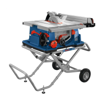
Table saw GTS 254
Starting current limitation ●
Weight according to EPTA-
Procedure01:2014
kg 24.4
Protection class
/ II
Dimensions (including detachable parts of the tool)
Widthxdepthxheight mm 690x620x100
0
Dimensions of suitable saw blades
Saw blade diameter mm 254
Base blade thickness mm <2.0
Min. tooth thickness/offset mm >2.4
Hole diameter mm 30
Maximum workpiece dimensions: (see "Maximum workpiece dimen-
sions", page22)
The specifications apply to a rated voltage [U] of 230 V. These spe-
cifications may vary at different voltages and in country-specific mod-
els.
Assembly
u Avoid starting the power tool unintentionally. The
mains plug must not be connected to the power supply
during assembly or when carrying out any kind of
work on the power tool.
Items included
Check to ensure that all the parts listed below have been
supplied before using the power tool for the first time:
– Table saw with mounted saw blade(28)
– "Power tool" fastening set(39) (8 fastening screws, 8
washers)
– Base unit(14)
– "Base unit" fastening set(37) (16 fastening screws, 16
washers, 16 securing rings, 16 nuts)
– Tilt protector(13)
– "Tilt protector" fastening set(38) (4 fastening screws, 8
washers, 4 securing rings, 4 nuts)
– Angle guide(3)
– Profile rail(50)
– "Profile rail" wing nut(51)
– Parallel guide(9)
– Additional parallel guide(47)
– "Additional parallel guide" fastening set(48) (2 fastening
screws, 2 wing nuts)
– Riving knife(27) with protective cover(6) fitted
– Anti-kickback pawls(7)
– Ring spanner(35)
– Hook spanner/open-ended spanner(36)
– Push stick(15)
– Table insert(8)
Note: Check the power tool for possible damage.
Before continuing to use the power tool, carefully check that
all protective devices or slightly damaged parts are working
perfectly and according to specifications. Check that the
moving parts are working perfectly and without jamming;
check whether any parts are damaged. All parts must be fit-
ted correctly and all the conditions necessary to ensure
smooth operation must be met.
If the protective devices or any parts become damaged, you
must have them properly repaired or replaced by an author-
ised service centre.
Stationary or flexible mounting
u To ensure safe handling, the power tool must be
mounted on a flat, stable work surface (e.g. work
bench) before use.
Assembly with base unit and tilt protector
(seefiguresa1−a3)
For assembly, use the "base unit"(37), "tilt protector"(38)
and "power tool"(39) fastening sets
– Screw the base unit(14) together. Tighten the screws
firmly.
– Screw the tilt protector(13) to the base unit.
– Place the power tool on the base unit so that the tilt pro-
tector points to the rear.
– Attach the power tool to the base unit. For this, use the
lateral holes (31) of the power tool as well as the holes in
the base unit.
Assembly without base unit (seefigureb)
– Use a suitable screwed connection to secure the power
tool to the work surface. The holes(32) are used for this
purpose.
Fitting individual components
– Carefully remove all parts included in the delivery from
their packaging.
– Remove all packing material from the power tool and the
accessories provided.
– Make sure that you remove the packaging material be-
neath the motor block.
The following parts of the tool are attached directly to the
housing: Anti-kickback pawls(7), ring spanner(35), hook
spanner/open-ended spanner(36), angle guide(3), parallel
guide(9), additional parallel guide(47) with fastening
set(48), protective cover(6), push stick(15), saw
blade(28).
– If you require one of these parts, remove it carefully from
its storage location.
Fitting the Riving Knife (seefiguresc)
Note: If necessary, clean all parts to be fitted before you po-
sition them.
– Remove the table insert(8) if necessary.
– Turn the crank(17) clockwise as far as possible so that
the saw blade(28) is in the highest possible position
above the saw table.
– Loosen the bolt(40) using the ring spanner(35).
1 609 92A 61K | (14.12.2020) Bosch Power Tools

 Loading...