1 689 989 4452019-07-01 | Robert Bosch GmbH
Product description | MTS 6531 | 9 en
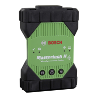
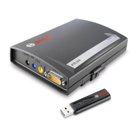
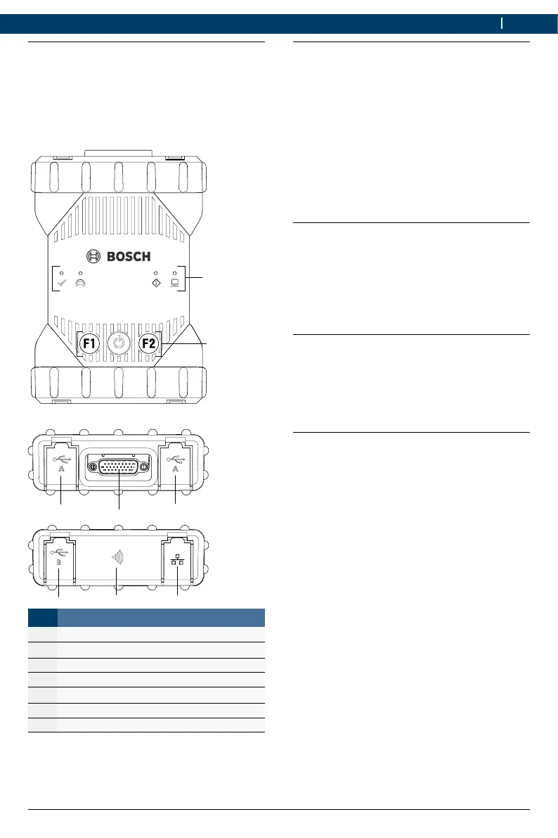
4.3 MTS 6531 Ports and cont-
rol elements
The MTS 6531 has various keys and
standardized ports for operating the device and
connecting it to the vehicle electrical system and
workshop network. These connectors and cont
-
rols are shown in the following illustrations.
DIAGNOSI
1
2
4
3
3
6
7
Item Description
1 LED status display
2 Control keys
3 2x USB-A port
4 Port for diagnostic connection cable
5 USB-B port
6 WiFi Adapter
7 Ethernet Port
4.4 Universal Serial Bus (USB) Port
The MTS 6531 has a fixed USB configura-
tion which cannot be changed. This ensures that
the MTS 6531 can always be connect
-
ed to a single computer running the software
"VCIManager" or the user software so you can
configure LAN or WLAN settings required by your
local network. In addition, it is important to note
that a USB connection is required to configure
the firmware on the MTS 6531, to pair
the computer with the MTS 6531 and to
update the firmware.
4.5 Wireless Local Area Network
(WLAN)
During setup and configuration of the WLAN
connection (802.11b/g/n), the MTS 6531
must be connected via USB to a computer run
-
ning the software "VCIManager" and be paired
with the computer.
4.6 Ethernet
During setup and configuration of the Ethernet
connection, the MTS 6531 must be
connected via USB to a computer running the
software "VCIManager" and be paired with the
computer.
4.7 Additional MTS 6531
Features
4.7.1 Data transfer
The connection between the MTS 6531
and the vehicle electronics is established via the
26-pin diagnostic connection cable.
 Loading...