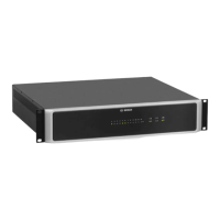
Figure 5.2: Stacking of devices using the supplied foot stands (example with 3 devices, rack mount rails are
used for the bottom device only)
The device must be protected from:
– Dripping water or spray
– Direct sunlight
– High ambient temperatures or immediate sources of heat
– High humidity
– Large dust deposits
– Strong vibrations
If these requirements cannot be guaranteed, the device must be regularly serviced to prevent
any outages that could occur as a result of negative ambient conditions. If a solid object or
fluid enters the housing, immediately disconnect the device from the voltage supply, and have
it serviced by an authorized technician before it is recommissioned.
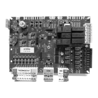
OM-1 Module installation
The optional OM-1 Module can be installed at the rear of the device. See item 2 in Rear, page
11.
Figure 5.3: Rear view of OM-1 Module
For information on how to install the OM-1 Module, refer to the OMNEO Module manual
(F01U308252).
5.1
PAVIRO Controller Installation | en 17
Operation manual 08-May-2017 | 04 | F01U306900

 Loading...