8:
5: CAN_L (-)
3:
2: CAN_GND
1: +24V DC
7:
8
1
4: CAN_H (+)
6:
GND
( )
AUDIO CALL STATION TO CONTROLLER -
AUDIO CALL STATION TO CONTROLLER +
AUDIO CONTROLLER TO CALL STATION -
AUDIO CONTROLLER TO CALL STATION +
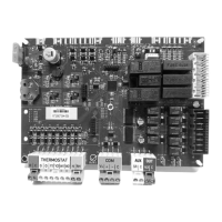
Figure 6.6: Pin assignment of CST BUS connector
For the CST BUS, the same requirements apply for the used line (length, cross section, etc.)
as for the CAN bus interface (see section CAN BUS). As the CST BUS includes the power
supply for all connected call stations or call station extensions, the power consumption must
be considered when selecting cable length or cross section. Please refer to the call station
manual for details about power consumption.
Notice!
The terminating of the CST BUS in the controller is configured via IRIS-Net during system
configuration.
Ethernet
Connecting the controller via the Ethernet interface allows the controller to communicate with
a PC. This not only allows simple configuration of the controller using the IRIS-Net software,
but it also allows you to operate and monitor the entire system.
LED status lights
The Ethernet interface of the controller has an orange and a green LED to display the status of
the Ethernet connection. If no network cable is connected, both LEDs remain unlit. The orange
connectivity LED on the left side of the Ethernet interface illuminates once the controller has
established an Ethernet connection with another device (e.g. an Ethernet switch). The green
network traffic LED on the right side of the Ethernet interface briefly illuminates each time
Ethernet data is transferred.
Crossover cable
When using a crossover cable to connect a controller with a PC directly, wire-pair 2 must be
swapped with wire-pair 3. This creates the necessary switch of sending and receiving lines;
with a hub/switch, this exchange is performed internally.
Supply voltage
6.4
6.5
24 en | Connection PAVIRO Controller
08-May-2017 | 04 | F01U306900 Operation manual

 Loading...