Do you have a question about the Bosch Rexroth 32 Series and is the answer not in the manual?
Important general information and safety instructions for operating and repairing the hydraulic pump.
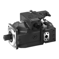
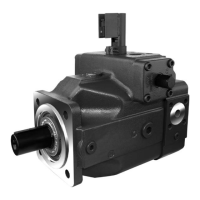
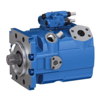
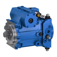
Detailed diagrams illustrating the internal components and layout of the hydraulic pump.
Essential guidelines and precautions to follow during all repair work on hydraulic aggregates.
Overview of available seal kits and pre-assembled component groups for maintenance and repair.
Details on the transition to Turcon seals for the positioning piston and its implications.
Identification and overview of different control devices and their types (old/new).
Illustrations and identification of boost pump, regulator valve, and pressure cut-off components.
Step-by-step instructions for properly sealing the drive shaft of the hydraulic pump.
Procedure for sealing the boost pump, including component checks and mounting instructions.
Instructions for sealing the control piston cover, emphasizing mechanical zero-position checks.
Detailed steps for removing and sealing the control piston cover, including checks and adjustments.
Procedure for removing and sealing the boost pressure valve, with notes on adjustment screws.
Instructions for sealing the pressure relief valve, including component checks and post-assembly verification.
Steps for sealing the pressure cut-off valve, including screw removal, checks, and post-assembly verification.
Procedures for sealing various control devices (DA, HD, EP, HW), including removal and checks.
Specific instructions for sealing the HW control device, including component checks.
Overview of older and newer versions of EP and HD control devices, with dimensional information.
Guidance on converting EP to HD versions, noting cover position and replacing tension springs.
Instructions for bleeding proportional solenoids and assembly details for Pole tube and eccentric pin.
Details on assembling the 4/3 way DA control device, including old and new versions.
Procedure for sealing and inspecting the regulator valve, focusing on the orifice and O-ring.
Steps to remove the control device from the pump assembly.
Procedure for removing the auxiliary pump, noting the importance of marking its assembly position.
Instructions for handling the port plate with auxiliary pump and identifying the direction of rotation.
Details on identifying counter-clockwise rotation and removing the wear plate during pump disassembly.
Steps for marking and removing the indexing screw, and loosening the connection plate fixation.
Procedure for pressing the cylinder and removing the hydraulic section of the rotary group.
Steps for removing radial seal rings, the drive shaft, and the swash plate assembly.
Instructions for marking the cover position and removing the control cover.
Steps for removing the cover, positioning ring, and spring-loaded parts during control dismantling.
Procedure for removing the piston and retaining the safety ring from the cylinder.
Guidelines for inspecting bearing cages, bearing cups, and bearing surfaces for wear.
Procedures for checking sliding surfaces and the return device for scoring or damage.
Checking sliding surfaces, cylinder bores, and splines for damage or wear.
Inspection of the positioning piston, cradle linkage, and related components for proper function.
Steps for assembling the positioning piston, including correct fitting of divided rings.
Instructions for mounting the housing with the Turcon-Glyd-ring, including the use of assembly tools.
Detailed process for fitting seal rings using assembly tools and installing guide thorns into the positioning piston.
Steps for inserting the positioning piston, bearing cups, and the complete swivel cradle into the housing.
Instructions for checking swivel bearing seating and fitting the joint pin during rotary group installation.
Guidance on using the holding device and a list of parts used in the rotary group installation.
Steps for assembling the drive shaft with bearings/seals and the piston with retaining plate.
Procedure for removing the holding device and fitting the cylinder complete with pistons and retaining device.
Instructions for installing the control plate for clockwise rotation, noting noise grooves.
Instructions for installing the control plate for counter-clockwise rotation, noting noise grooves.
Steps for inserting the control plate for counter-clockwise rotation and assembling the connection plate.
Installing the control plate for EP, HD, and HW types, noting rotation direction and fixing pins.
Procedure for screwing in the plug and placing the port block with control plate for final assembly.
Instructions for mounting the auxiliary pump and control unit, including torque specifications.
Table specifying tightening torques for shaft screws based on thread size and tensile strength class.
Table detailing tightening torques for plugs with internal hexagon and profile seal rings.
Table of tightening torques for plugs with internal hexagon, O-ring, and SAE threads.
Specifications for tightening torques for SEAL-LOCK sealing nuts.
Table of tightening torques for A4V nozzles (orifices), differentiating between old and new specifications.
General guidelines for safe operation, including familiarization with the machine and personal protective equipment.
Pre-operation checks including operating instructions, fault checks, and securing the machine.
Procedures for starting the machine safely, including lever positions and battery connections.
Critical safety warnings regarding high hydraulic pressure, leakages, and working on the system.
Procedure for adjusting the low pressure (boost pressure) valve at operating temperature.
Instructions for adjusting the mechanical zero position, connecting control chambers and pressure gauges.
Procedure for adjusting the hydraulic zero position using pressure gauges and eccentric adjustment.
Guidelines for adjusting HP valves, emphasizing 10% higher settings and checking both valves.
Procedure for adjusting the pressure cut-off, including blocking and setting screw operations.
Explanation of the bypass function and instructions for adjusting the bypass valve for free oil circulation.
Procedure for checking DA control data and observing the block position during adjustment.
Instructions for adjusting the begin and end of control for DA regulation, noting eccentric adjustment.
| Brand | Bosch |
|---|---|
| Model | Rexroth 32 Series |
| Category | Water Pump |
| Language | English |