p Maximum permitted input pressure on the Ex-p controller 3 bar
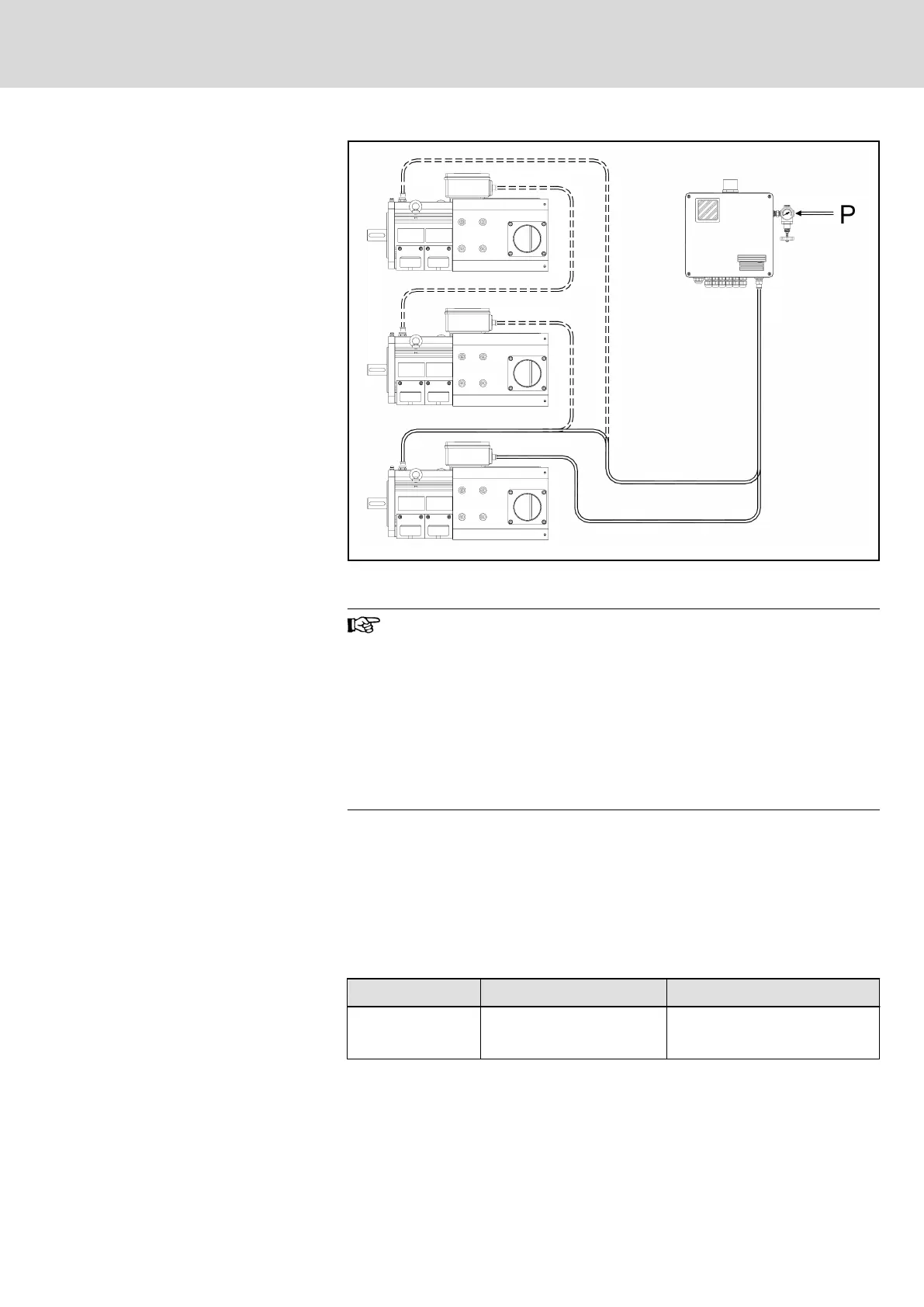
Fig. 9-13: Purge gas connection diagram
● If several motors should be operated with a controller, con‐
nect them in series when connecting the scavenging gas
tubes (Fig. 9-13)!
● If the control device is failed and an emergency power sup‐
ply of the system with scavenging gas is necessary, please
refer to the details in DIN EN 60079-2 (VDE 0170-3) in chap‐
ter 9 “Supply with protective gas”.
– We recommend an emergency power supply, if it will
be necessary to keep up operation of electrival devices
in an emergency case.
Purge gas connection
Proceed as follows when connecting the purge gas ducts:
1. Remove the protective stoppers of the scavenging bores on the motor.
2. Fasten the purge gas ducts via the purge gas connections in the appro‐
priate connection threads at the motor (heed the flow direction).
3. Heed the following details about the permitted screw-in depth of the
scavenging gas connections and tighten them with a tightening torque
according to the details of the manufacturer.
Motor frame size Connection thread permitted screw-in depth
100 ... 225 G1/4”
min. 12 mm
max. 14 mm
Tab. 9-10: Connection threads of the scavenging gas bores on the motor
Scavenging gas
Only inert gas or cleaned and dried industrial air are permitted as scavenging
gas.
DOK-MOTOR*-IDYN*A*EXPD-IB05-EN-P Bosch Rexroth AG 51/69
Rexroth MAD and MAF Motors in EX px d Design acc. to ATEX Directive 2014/34/EU
Connection system