Electric Drives
and Controls
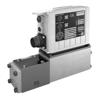
3-1Bosch Rexroth AGPSI 6500.xxx1070087059 / 02
Electric Connection
3 Electric Connection
. For detailed information on the electric connection of a single unit,
please refer to the
D “Control and I/O Level, Technical Information” documentation
of the particular unit types (PSx 6xxx.100, PSx 6xxx.190 and PSx
6xxx.000) and
D in the manual of the power section used (see page 1-1).
The present manual provides supplements to this information that
is essential for using the master-slave mode.
3.1 Power, Transformer and Temperature Contact
It is not necessary to turn on the master and the connected slaves simul-
taneously (logic supply at X4).
It should, however, be noted that the master signals “Ready” to the hig-
her-order control logic only if all connected slaves signal “Ready” to the
master (logic/power supply present, connections to the master establis-
hed, etc.).
L Ensure that all connection lines are appropriately dimensioned!
L Ensure that the stop circuit is interrupted even in case of a slave failure!
L Only welding transformers with identical electric data may be connected
in parallel.
L Only use connection lines of the same length for all parallel transformers
in the primary circuit.
L Only use connection lines of the same length for all parallel transformers
in the secondary circuit. If possible, connect the individual current bran-
ches in parallel shortly before the electrodes.
L Connect the temperature contacts of all transformers used in series and
connect the complete circuit always to the master (X3, terminals 4 and
5).
The remperature input of a unit that is configured as a slave is deactiva-
ted automatically!!

 Loading...