6720818454 (2016/02) US SSB
16 | Installation
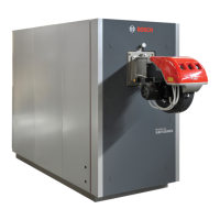
4.4.1 Low water cut off
A low water cut off (LWCO) is installed in the boiler, the manual reset
button is located on the front of the internal sliding wiring center.
To check the functionality of LWCO press the test button (the top button
shown in Fig. 10). The LED on the block will light and in the screen will
appear the error “MN: Low Water Cutoff Error”. At this point press the
reset button (the bottom button). The LED will turn off.
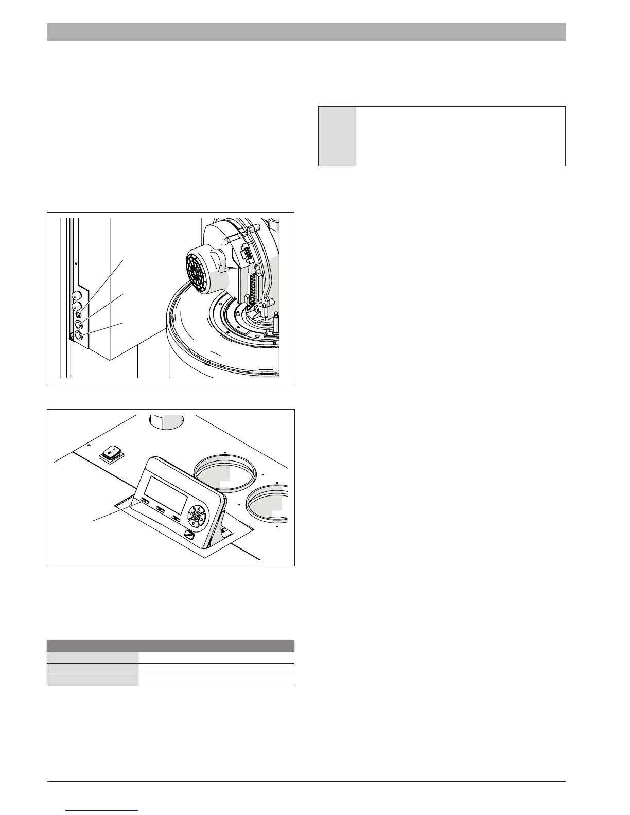
4.4.2 High limit safety switch
A high limit safety switch is installed in the boiler. To simulate a high limit
lockout at 208°F press the “MENU” and “OK” buttons simultaneously for
10 seconds. The control will display “MN: Max. Thermostat Lock Error”.
At this point press the reset button on the removable display to restart the
boiler.
Fig. 10
Fig. 11
4.4.3 Pressure relief valve (PRV)
The boiler is supplied with a pressure relief valve (PRV). The relief
pressure for each valve for each model of the boiler is shown in the
following table:
Boiler model Relief Pressure
SSB255 30 psi (2.07 bar)
SSB399 30 psi (2.07 bar)
SSB512 75 psi (5.17 bar)
A 75psi pressure relief valve can be purchased separately and eld
installed.
The pressure relief valve (PRV) must be piped to a suitable drain to
prevent injury if the valve releases. Use a pipe of the same diameter of
the outlet of the valve
4.4.4 Expansion tank
An expansion tank must be installed in the hydraulic system. The
expansion tank must be properly sized for the boiler and the system
volume, temperature and pressure.
WARNING: An undersized expansion tank will cause
leakage of water from the pressure relief valve and
introduce fresh water into the system. Excessive addition of
makeup water can cause corrosion of metallic components
and compromise the functionality of the boiler.
Refer to instructions provided by the manufacturer of the expansion tank
for details on its installation and sizing.
LED
Test
Reset
Reset