SSB 6720818454 (2016/02) US
Product description | 9
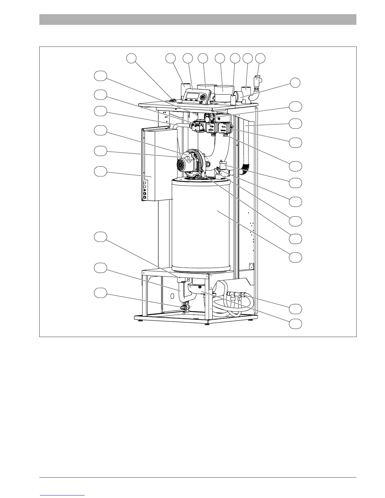
2.6 Main components
Fig. 5 SSB512 (main components)
[1] Main power switch
[2] System return
[3] Removable display
[4] Flue exhaust
[5] Intake air
[6] Gas inlet
[7] System supply
[8] Pressure Relief Valve
[9] Tridicator
[10] Air pressure switch
[11] Heat exchanger supply pipe
[12] Max pressure switch [For SSB 512 Only]
[13] Min pressure switch [For SSB 512 only]. Location should be burner
side of gas valve.
[14] Automatic air vent
[15] Low water cut off probe
[16] High limit temp. safety switch
[17] Spark electrode
[18] Heat exchanger
[19] Condensate manifold
[20] Air pressure switch connection
[21] Low point drain valve
[22] Heat exchanger return pipe
[23] Return temperature probe
[24] Wiring Control Panel
[25] Main shut off gas valve
[26] Fan
[27] Gas pipe
[28] Gas valve
[29] Flue gas probe
1 2 3 4 65 7 8
20
21
22
23
24
25
26
27
29
28
18
19
17
16
15
14
13
12
9
11
10