SSB 6720818454 (2016/02) US
Commissioning (for single boiler application) | 39
5.7 Adjusting and setting CO
2
limits
NOTICE:
Please verify parameter 99 is to be set rst.
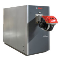
Insert a combustion analyzer probe into the test port “A” as shown in Fig.
67.
Fig. 67
► Press “Menu” key.
► Select “System Test”:
► In “System test” menu select “High Power” using “Up/Down” keys and
press “OK”:
ù
e “Test Status” switches to “on” and in the display will appear the fan speed. Wait 2 or 3 minutes to to reach steady state conditions and record the CO2 value.
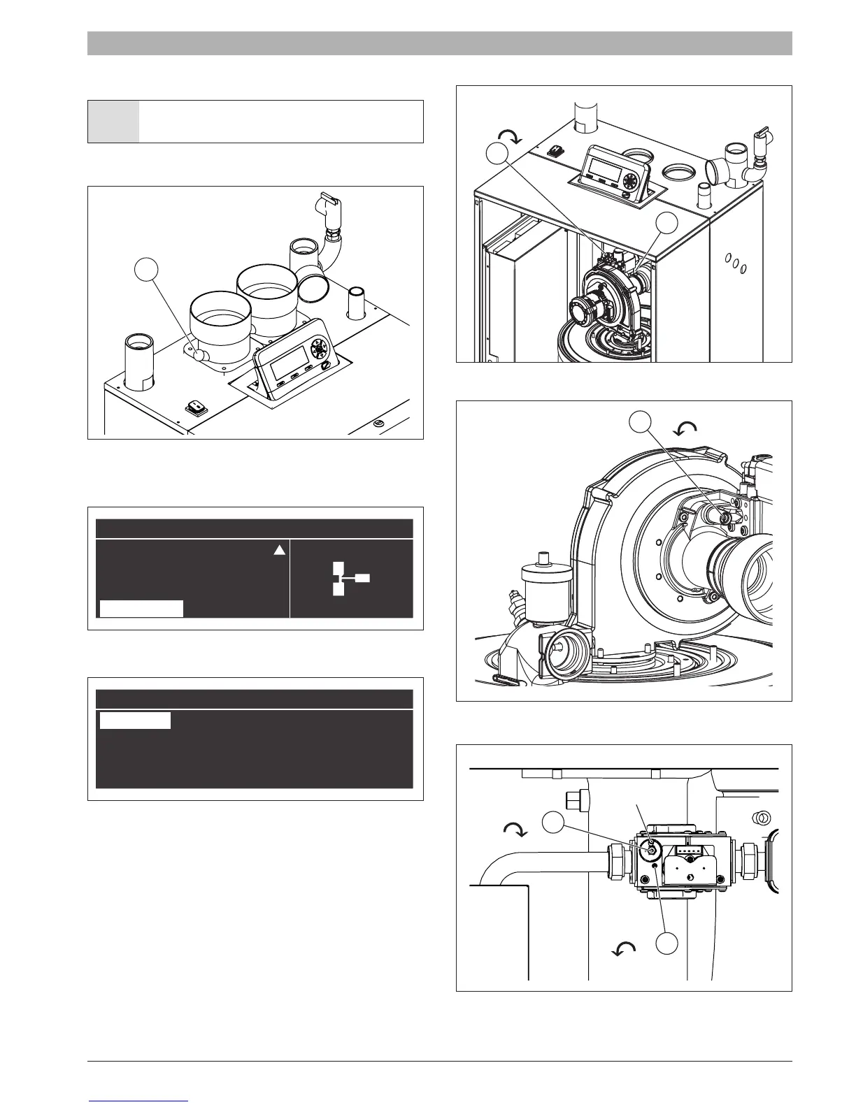
To adjust the CO2 value at the maximum power turn the screw “A” shown
in Fig. 69 (for SSB255) and in Fig. 70 (for SSB399 and SSB512), allen
type wrench is necessary for this adjustment.
Fig. 68 Gas valve screw regulation for SSB255
Fig. 69 Gas valve screw regulation for SSB255
Fig. 70 Gas valve screw regulation for SSB399 and SSB512
(*) Balancing tube shown removed for clarity.
A
Menu
Domestic Hot Water
Information
Settings
System Test
System Test
Test State High Power
Fan Speed 0 rpm
Ionisation 0.0 μA
B
A
CO2 +
A
CO2 +
CO2 +
CO2 +
B
A
(*)