Use | 51
6 720 801 512 (2013/10)Tronic 1000 T
▶ Use the appropriate connection accessories to do the hydraulic
connection to the appliance.
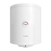
Fig. 7 Water connection
[1] Galvanic insulator
[2] Hot water outlet
[3] Safety valve
[4] Drain connection
[5] Cut off valve
[6] Reduction valve
[7] Anti-reduction valve
[8] Connection to the water line
In the case of freezing:
▶ Switch off the appliance.
▶ Purge the appliance ( chapter 5.4).
4.4 Electric connection
All adjusting devices, verification and safety mechanisms were
submitted to a rigorous test in factory and are ready to work.
▶ Connect the power cable (without plug) to the building electrical
supply using a junction box. Ensure the connection of the earth cable.
4.5 Start-up
▶ Verify that the appliance has been correctly installed and assembled.
▶ Open the water inlet valves.
▶ Open all the hot water taps in order to ensure all the air is out of the
connections.
▶ Control the tightness of all the connections and ensure that the
appliance fills to its full capacity.
▶ Connect the appliance to the electric current.
▶ Inform the customer of any user information of the appliance and
handling.
5Use
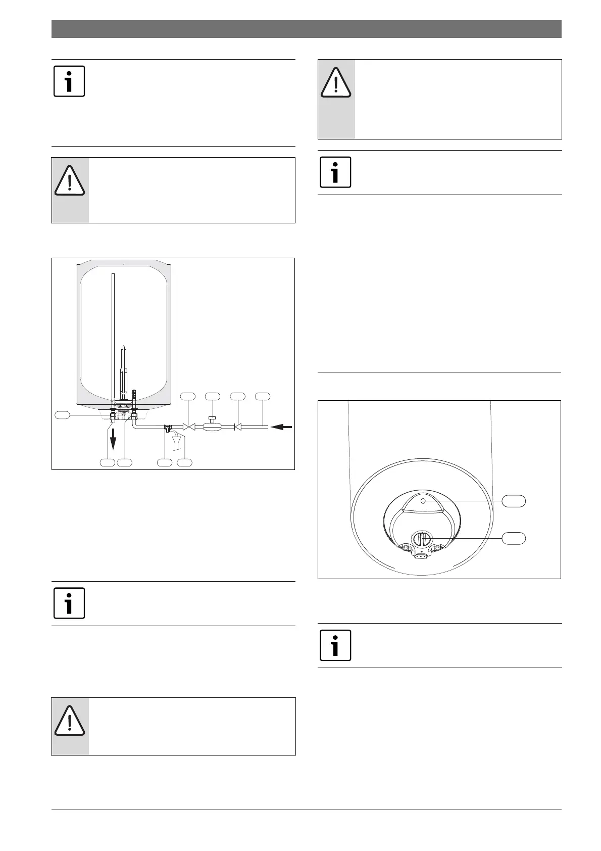
Fig. 8 User interface
[1] Indicator
[2] Temperature selector
5.1 User information from the technician
▶ The technician should inform the user of the functioning and handling
procedures as well as the device maintenance.Inform the user of
regular maintenance procedures; the functioning and life span and
the factors pertinent to this. Inform the user of the need to check,
monthly the correct functioning / working order of the security valve,
opening the lever manually.
▶ During the operation of the device, water can be released by the
safety purge. Keep the purge hose outlet free from any blockage.
If the pressure at the cold water inlet is superior to that of
80% of the maximum pressure of the appliance at, ie: 6,4
bar, install a reducing valve (FIg. 7).
The safety valves will trigger every time the water
pressure in the appliance is superior to that of 6,4 bar,
for which it will be necessary to foresee a way to channel
the draining of the water.
NOTICE:
NEVER OBSTRUCT THE PURGE OUTLET OF THE SAFETY
VALVE.
Never install any accessory between the safety valve and
the cold-water inlet (right hands side) of the appliance.
In order to avoid problems caused by sudden pressure
changes, we recommend the installation of a anti-
reduction valve at the appliance (Fig. 7, [7]).
DANGER:
By electrical discharge!
▶ Before working on the electrical components, firstly
cut the power, (fuse, circuit breaker or other).
6720643873-05.1V
3 4
5 6 7 8
2
1
1
CAUTION:
Electrical protection!
▶ The appliance should dispose of an independent
connection to the DB board (electric board),
protected by a 30 mA differential circuit breaker and
earthing.
The electrical connection must be realized in accordance
with the current country laws regarding electrical
installations.
The electrical connection must be done in accordance
with the current domestic electrical compliance
installation regulations.
 Loading...