16 | Commissioning
Gaz 6000 W8 716 473 216 (2014/09)
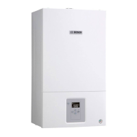
7.1 Displays
Fig. 19 Displays
[1] Burner operation
[2] Fault display/standby mode display
[3] Heating mode active
[4] DHW heating active
[5] Summer mode active
[6] Service Mode
[7] Temperature display (in °C)
7.2 Before commissioning
▶ Adjust pre-charge pressure of expansion vessel to static head of the
heating system ( page 10).
▶ Open the automatic air vent valve (leave open) ( Fig. 18, [7],
page 15).
▶ Open all system radiator valves.
▶ Open the heating flow valve and heating return valve ( Fig. 18, [6]
and [2], page 15).
▶ Fill the heating system to 1 - 2 bar and close the fill valve.
▶ Bleed radiators.
▶ Top up heating system to pressure of 1 - 2 bar.
▶ Check that the gas type specified on the type plate matches that of the
gas supply (see Fig. 24).
▶ Open the gas valve ( Fig. 18, [4]).
▶ Plug in the power plug: the appliance enters standby mode.
7.3 Switching the appliance on/off
Initial switching on/setting the fan stage
At the factory, fan stage 0 is selected, i.e. fan and burner will not start.
▶ Start the appliance at the standby key (Fig. 20).
The following fault display is shown:
Fig. 20
Set fan stage:
▶ Determine a suitable fan stage.
▶ Hold down “Back”, + and – at the same time until L.1 is shown on the
display.
▶ Press + until L.2 is shown on the display.
▶ Press OK to make settings in menu 2.
▶ Press + or – to call up service function 2.b.d ( page 21).
▶ Press OK to switch to the service function.
The value flashes on the display.
▶ Press + or – to set the required value.
▶ Hold down OK until the selected service function appears on the
display.
The display switches to the selected service function automatically.
▶ Press standby.
The boiler returns to standard mode.
Switching on
▶ Start the appliance at the standby key.
The display shows the heating water flow temperature.
Switching off/standby mode
▶ Shut down the appliance at the standby key.
Only the warning symbol continues to be displayed.
▶ If the appliance is to be switched off for a longer period of time:
observe correct frost protection procedures ( chapter 7.8).
Fig. 21
7.4 Setting the maximum flow temperature
The maximum flow temperature can be set between 40 °C and
approx. 82 °C. The current flow temperature is shown on the display.
▶ Keep pressing – until the symbol appears on the display.
▶ Press OK.
The set maximum flow temperature is displayed.
▶ Press + or – to set the required maximum flow temperature.
▶ Press OK to save the setting.
The display shows the current flow temperature.
You can find typical maximum flow temperatures in Tab. 10.
When the burner is active in heating mode, the symbol and the
burner symbol appear on the display.
NOTICE: Commissioning without water will destroy the
appliance.
▶ Only operate the appliance once it has been filled with
water.
6 720 806 640-05.2O
32
1
4 5 6 7
6 720 806 640-18.3O
The appliance has an anti-seizing function which
prevents the heating circuit pump and the 3-way valve
seizing up following long periods of inactivity.
The anti-seizing function remains active during standby
mode.
When selecting . ., heating mode is disabled (
appears on the display, summer mode).
Flow temperature Sample application
. . ( symbol appears) Summer mode
Approx. 75 °C Radiator heating system
approx. 82 °C Convector heating system
Table 10 Maximum flow temperature
ok
6 720 806 464-06.2O

 Loading...