22 | Pre-installation AU/NZ
6 720 646 195a (2010/11)
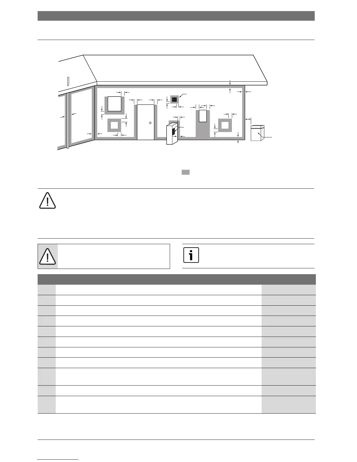
3.9 Flue terminal positions
Fig. 18 Flue terminal positions
6720646195-02.1Wo
Use as a guide only. Refer to AS5601 or local gas fitting rules for specific locations
T = Flue terminal M = Gas meter W = Window
I = Mechanical air inlet Shaded area indicates prohibited areaP = Electricity meter or fuse box
f
c
n
k
k
j
jj
h
h
e
T
e
h
T
g
P
W
d
b
d
T
g
c
a
M
Door
I
NOTE:
B The location of the flue terminal must comply with the clearances shown on this page. If you are unsure
about clearances not indicated here, in general refer to AS5601 or your local authority. In Western
Australia refer to the SECWA rules and regulations.
B All measurements are the minimum clearances required.
B Terminals must be positioned so to avoid combustion products entering the building.
NOTE: Install a fire proof back board if
installing on combustible surfaces.
The fixing method must be sufficient to hold
the weight of the boiler.
Ref. Item Min. Clearance mm
a Below eaves, balconies and other projections (Appliances over 50MJ/h) 300
b From the ground, above a balcony or other surface 300
c From a return wall or external corner 300
d From a gas meter 1000
e From an electricity meter or fusebox/breaker panel 500
f From a drain pipe or soil pipe 75
g Horizontally from any building structure or obstruction facing a flue terminal 500
h From any other flue terminal, cowl or combustion air intake 300
j Horizontally from any opening window, door, non-mechanical air inlet or other
opening into a building with the exception of sub-floor ventilation
300
k From a mechanical air inlet including a spa blower. 1000
n Vertically below an opening window, non-mechanical air inlet or any other opening
into a building with the exception of sub-floor ventilation
500
Tab. 20
 Loading...