Service and spares | 47AU/NZ
6 720 646 195a (2010/11)
6.8 Replacement of parts
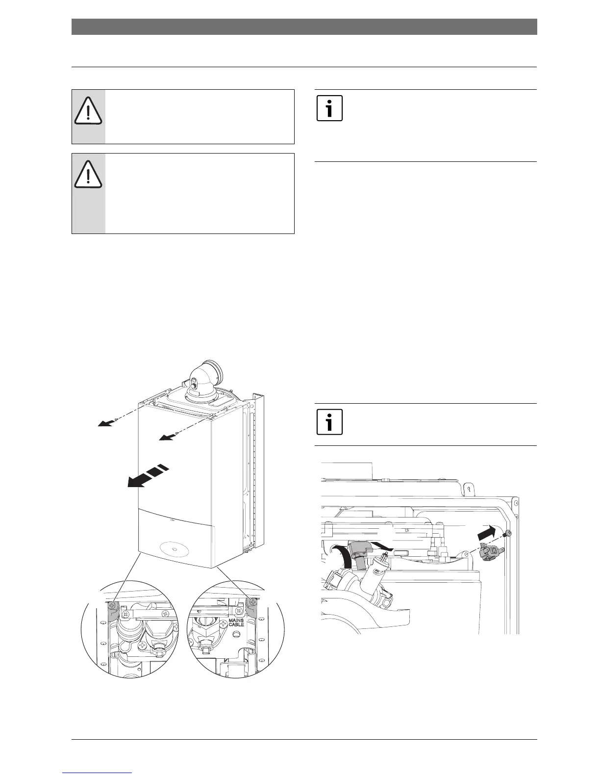
6.8.1 Removing outer case
1. Undo the two screws securing the top of the boiler
casing.
2. Undo the two screws securing the bottom of the
boiler casing.
B Pull case forward and remove.
To remove bottom tray, pull forward on the tag on the
underside of the tray.
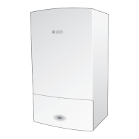
Fig. 78 Remove outer case
6.8.2 Primary sensor
Refer to figure 79 for removal.
1. Remove electrical connection by pulling upwards.
Squeeze retaining clip on plastic moulding of sensor
and pull back and up until clear of pocket in heat
exchanger.
2. Pull forward to remove completely.
B Coat new sensor with heat conductive paste and
replace.
6.8.3 Overheat thermostat
Refer to figure 79 for removal.
B Remove two electrical connectors from thermostat.
3. Slacken and remove fixing screw and thermostat (3).
B When replacing ensure thermostat sits correctly on
surface of the casting with the left hand side of
thermostat sitting up against the shoulder.
Fig. 79 Primary sensor and overheat thermostat
CAUTION: Turn off the gas supply and
isolate the mains supplies before starting
any work and observe all relevant safety
precautions.
NOTE: Replacing components
B After replacement of any components
always check for gas tightness where
relevant and carry out functional checks
as described in commissioning. Damaged
O-rings or gaskets must be replaced.
1.
1.
2.
2.
6720643895-57.1Wo
To gain access to the following components
the outer case has to be removed:
B Primary sensor
B Overheat thermostat
B Flue limit thermostat
It is essential that the mating surface of the
thermostat is coated with heat conductive
paste.
6720643895-69.1Wo
1.
2.
3.



 To Next Page